Series and Parallel Circuit Simulator
Set up series and parallel circuits with a battery, bulbs and switches, and read each bulb’s voltage, current and brightness, solved with Kirchhoff’s laws.
Simulator
Tap a switch to open or close it, or a load to move the meters to it. With the scene focused, 1, 2 and 3 flip the switches and the arrow keys move the meters. Space plays and pauses.
- Battery current What an ammeter beside the battery reads: the current through the whole circuit.
- 0.333 A
- Circuit resistance Everything outside the battery, found as terminal voltage over current.
- 18 Ω
- Terminal voltage The EMF less the current times the internal resistance.
- 6 V
- Voltmeter, bulb 1
- 4 V
- Ammeter, bulb 1
- 0.333 A
- Power, bulb 1 I²R, which is what sets a bulb’s brightness.
- 1.33 W
| Part | Resistance | Voltage | Current | Power |
|---|---|---|---|---|
| Bulb 1 (L1) | 12 Ω | 4 V | 0.333 A | 1.33 W |
| Bulb 2 (L2) | 12 Ω | 2 V | 0.167 A | 0.333 W |
| Bulb 3 (L3) | 12 Ω | 2 V | 0.167 A | 0.333 W |
| Battery | 0 Ω inside | 6 V | 0.333 A | 2 W |
- Current law: the current into a junction equals the current out:
I₂ + I₃ = I₁,0.167 A + 0.167 A = 0.333 A. - Voltage law: round a loop the voltages across the loads add up to the battery’s terminal voltage:
V₁ + V₂ = V,4 V + 2 V = 6 V.
The battery row’s power is its EMF times the current, everything the cell converts. With internal resistance above zero, the part that heats the battery is the difference between it and the loads’ total.
Citing this tool
Last updated . Add the date you accessed it as well, which a citation of a page that can change asks for. If a specific result matters, cite the permalink from the tool’s share row instead of this page: it reproduces the exact parameters.
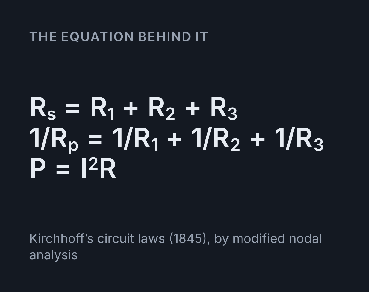
The equation
Kirchhoff’s circuit laws (1845), by modified nodal analysis
How current and voltage behave in series and parallel circuits
In a series circuit the same current flows through every component and the battery’s voltage
is shared between them, so the resistances add: R = R₁ + R₂ + R₃. In a parallel
circuit every branch gets the full voltage and the branch currents add, so the reciprocals
add: 1/R = 1/R₁ + 1/R₂ + 1/R₃. A bulb’s brightness follows the power it
converts, P = I²R, which is why the same bulb glows differently in the two.
This simulator builds four circuits from a battery, bulbs or resistors and switches, and solves each one exactly with Kirchhoff’s circuit laws (1845): the current into every junction equals the current out, and the voltages round every loop add up to the battery’s. It writes them as one set of simultaneous equations by modified nodal analysis, the method of Ho, Ruehli and Brennan (1975) that circuit simulation programs use, so it also handles the bridge circuit that the series and parallel rules cannot reduce.
Using the simulator
Choose a circuit: series, parallel, series and parallel combined, or a Wheatstone bridge. Set the battery’s EMF, its internal resistance and each load’s resistance, and open or close the switches with their controls, by tapping them on the drawing, or with the keys 1, 2 and 3 once the drawing has focus. The voltmeter hangs across one load and the ammeter sits in line with it; choose which under Meters on, tap a load, or move them with the arrow keys.
The moving dots are the current, drawn in the conventional direction from the battery’s positive terminal round to its negative one, moving faster where more current flows. Bulbs are drawn brighter as their power rises and are fully lit at 3 W. The table under the drawing lists the voltage, current and power of every load, and the lines under it state Kirchhoff’s laws with the circuit’s own numbers.
Worked example: one bulb in series with two in parallel
The simulator opens with three identical 12 Ω bulbs on a 6 V battery: bulb 1 in series with
bulbs 2 and 3, which are in parallel with each other. The parallel pair is
1/(1/12 + 1/12) = 6 Ω, so the whole circuit is 12 + 6 = 18 Ω and the
battery supplies I = 6/18 = 0.333 A. Bulb 1 carries all of it and takes
0.333 × 12 = 4 V, which leaves 2 V across the pair. Each of bulbs 2 and 3 then
carries 0.167 A, half the current, and the powers are 1.33 W for bulb 1 and 0.333 W for each
of the others, so bulb 1 is by far the brightest.
Now open S3. Bulb 3 goes out, the circuit becomes two 12 Ω bulbs in series,
24 Ω, and the current falls to 6/24 = 0.25 A. Bulb 1 dims from
1.33 W to 0.75 W, but bulb 2 brightens from 0.333 W to 0.75 W, because it now has 3 V across
it instead of 2 V. Switching a bulb off made another one brighter: removing a parallel branch
raised the circuit’s resistance, which moved voltage off bulb 1 and onto bulb 2.
Why bulbs in series are dimmer than bulbs in parallel
Three identical 12 Ω bulbs in series on 6 V share it equally, 2 V each, and carry 0.167 A, so each converts 0.333 W, a ninth of the 3 W one bulb alone would. In parallel each bulb has the whole 6 V across it, carries 0.5 A and converts 3 W, as bright as a single bulb, while the battery has to supply 1.5 A, nine times the series circuit’s 0.167 A. Parallel wiring is why the lights and sockets in a house each get the full supply voltage and switch on and off without affecting one another, as the parallel circuit’s S2 and S3 show.
Kirchhoff’s laws and the Wheatstone bridge
The bridge is two voltage dividers side by side, loads 1 and 2 on the left and 3 and 4 on the
right, with load 5 joining their midpoints. When R₁/R₂ = R₃/R₄ the two midpoints
sit at the same voltage and no current flows through load 5 whatever its resistance, which is
how a bridge measures an unknown resistance against three known ones. Try 10, 20, 15 and
30 Ω: 10 × 30 = 20 × 15, and bulb 5 stays dark.
Unbalance it with 10, 20, 30, 40 and 50 Ω on 6 V and load 5 carries 7.74 mA from the left midpoint to the right. No two of those resistors are in series or in parallel, so there is no way to add them up. Kirchhoff’s current law at each midpoint gives two equations in the two unknown midpoint voltages, and solving them gives the battery current, 0.286 A, which the series and parallel rules cannot.
What internal resistance does
A real cell has resistance inside it, r, so the current it drives is
I = E/(R + r) and the voltage at its terminals is V = E − Ir, less
than its EMF whenever current flows. Set 1 Ω on the opening circuit and the current falls to
6/19 = 0.316 A with 5.68 V at the terminals. The more current a circuit draws,
the more voltage is lost inside the cell, so adding bulbs in parallel no longer leaves the
others untouched.
What this does not cover
Every load is a fixed resistance. A real filament bulb is not ohmic: tungsten’s resistance rises steeply as it heats, so a bulb on a low voltage draws more current than a fixed resistance would, and brightness here stands in for power rather than modelling light. The meters are ideal, the voltmeter drawing no current and the ammeter adding no resistance, and the wires and closed switches have none either. Nothing changes with time: a DC circuit settles the moment a switch moves, so for what happens during that moment, with a capacitor in the circuit, use the RC charge and discharge simulator.
Common mistakes
- Thinking current is used up by the bulbs. The ammeter reads the same on either side of a series bulb. What the bulb converts is energy, carried by the current, not the current itself.
- Adding parallel resistances directly. Two 12 Ω bulbs in parallel make 6 Ω, less than either one, because the second branch gives the current another path.
- Connecting a voltmeter in series or an ammeter in parallel. The voltmeter goes across a component and the ammeter in line with it, as the drawing shows.
- Expecting a bigger resistance to be brighter in parallel. With the same
voltage across every branch,
P = V²/R, so the smallest resistance converts the most power. In series it is the other way round,P = I²Rwith the same current. - Assuming an open switch has no voltage across it. With S1 open in the series circuit no current flows, the bulbs have 0 V across them, and the whole 6 V sits across the gap in the switch.
To total a network of resistors quickly, use the resistor network calculator; for one component at a time, the Ohm’s law calculator; and to practise, the electricity practice problems.
Model and assumptions
- Method
- Exact expression, no time stepping
- Repeatability
- Deterministic. The same link gives the same numbers on any machine.
What it assumes
- Kirchhoff’s current law at every junction and each part’s own voltage rule are solved together as one linear system by modified nodal analysis, so every reading is exact rather than stepped.
- Every bulb and resistor is a fixed resistance, and a bulb’s brightness is drawn from its power alone, fully lit at 3 W, rather than from a model of the light it gives.
- Wires, closed switches and the ammeter have no resistance, an open switch conducts nothing, and the voltmeter draws no current.
- The battery is a constant EMF in series with a fixed internal resistance, and nothing changes with time: the circuit settles the instant a switch moves, and the moving dots only picture the current.
Where it stops holding. Real filament bulbs, whose resistance rises steeply as they heat, so their current is not proportional to their voltage, and the moment after a switch moves, when capacitance and inductance in a real circuit make the current take time to settle. The RC Charge and Discharge Simulator is the right tool there.
Numerical accuracy
No method error to report: the result is a closed-form expression evaluated directly, with no time stepping to accumulate error. What remains is double-precision rounding, of order one part in 10^16 per operation.
Common questions
Why are bulbs in parallel brighter than bulbs in series?
Because each bulb in parallel has the whole battery voltage across it, while bulbs in series share it. Three identical 12 Ω bulbs on a 6 V battery get 2 V and 0.333 W each in series, but 6 V and 3 W each in parallel, nine times the power, and a bulb’s brightness follows its power.
What happens to the other bulbs when one is switched off?
It depends on the circuit. In series the loop is broken and every bulb goes out. In parallel, with an ideal battery, the others carry on exactly as before. In a mixed circuit the rest change: with one bulb in series with two in parallel, switching off one of the pair dims the series bulb and brightens the one left in parallel.
Where do the voltmeter and the ammeter go?
The voltmeter goes across a component, in parallel with it, and the ammeter in series, in line with it. An ideal voltmeter draws no current and an ideal ammeter has no resistance, so neither changes what it measures, which is how this simulator treats them.
What are Kirchhoff’s laws?
Two rules that between them solve any circuit. The current law says the current flowing into a junction equals the current flowing out, because charge is conserved. The voltage law says the voltages round any closed loop add up to zero, so the loads’ voltages add up to the battery’s, because energy is conserved. Gustav Kirchhoff published them in 1845.
When is a Wheatstone bridge balanced?
When R₁/R₂ = R₃/R₄. The two midpoints are then at the same voltage, so no current flows through the middle arm whatever its resistance. With 10, 20, 15 and 30 Ω the bridge is balanced, since 10 × 30 = 20 × 15, and the bulb across the middle stays dark.
Is a real bulb a fixed resistance?
No. A filament’s resistance rises steeply as it heats, so its current is not proportional to its voltage. This simulator treats every bulb as a fixed resistance, the model school circuit questions use, and draws the brightness from the power rather than modelling the light.