RC Charge and Discharge Simulator
Watch a capacitor charge and discharge through a resistor. Adjust R, C and the supply to see what moves the time constant and what leaves it alone.
Simulator
- Time constant R times C. Independent of the supply voltage.
- 100 ms
- Capacitor now 0 percent of the way there.
- 0 V
- Current now
- 5 mA
- Resistor now The supply minus the capacitor, at every instant.
- 5 V
- Stored energy Ends at 1.25 mJ.
- 0 mJ
- Charging efficiency Exactly half the supplied energy always becomes heat, whatever the resistance.
- 50 %
- Capacitor
- Resistor
Citing this tool
Last updated . Add the date you accessed it as well, which a citation of a page that can change asks for. If a specific result matters, cite the permalink from the tool’s share row instead of this page: it reproduces the exact parameters.
The equation
Exponential RC response, from Kirchhoff’s laws
Where the exponential comes from
The circuit is a loop, so at every instant the supply voltage has to be
split between the resistor and the capacitor. That single constraint is
the whole story. An empty capacitor takes none of it, leaving all of the
supply across the resistor, which by Ohm’s law gives the largest current
the circuit will ever see: simply V/R.
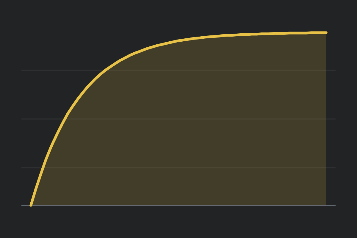
That current carries charge onto the capacitor, so its voltage rises, which leaves less for the resistor, which reduces the current, which slows the charging. The rate of progress is proportional to how far there is left to go, and that is the defining property of exponential approach. It is why the curve is steep at the start and flattens forever without ever landing.
What the time constant is, and what it is not
The time constant τ = RC is the time to cover 63.2 percent of
the remaining gap. The particular number is 1 - 1/e, and the
useful thing about it is that it does not depend on the values: after one
time constant every RC circuit in existence is 63.2 percent of the way
there.
| Elapsed | Charging | Discharging |
|---|---|---|
| 1τ | 63.2% | 36.8% left |
| 2τ | 86.5% | 13.5% left |
| 3τ | 95.0% | 5.0% left |
| 5τ | 99.3% | 0.7% left |
Notice what is missing from RC: the supply voltage. Raise it
and every voltage in the circuit scales up, including the starting
current, so the fraction completed at any moment is unchanged. Move the
supply slider and watch the time constant readout sit still while the
voltages change. That is the fastest way to convince yourself the two are
independent.
Charging always wastes exactly half the energy
This is the result worth taking away, because it is genuinely surprising and it takes three lines to prove.
The supply pushes a total charge of Q = CV around the loop,
and it does so at a fixed potential difference V, so the
energy it delivers is QV = CV². The capacitor ends up storing
½CV², which is half as much. The shortfall is not an error:
the capacitor’s own voltage climbed from zero to V while
filling, so on average it was only opposing half the supply. Everything
not stored went into the resistor as heat.
No resistance appears anywhere in that argument. Halving R
charges the capacitor twice as fast and the resistor still dissipates
exactly the same total energy, just over half the time. You cannot improve
the efficiency of this circuit by choosing better components, which is
precisely why switched-mode converters exist and why they do not charge
capacitors this way.
Discharging is the same curve, reversed
Switch to discharging and the supply leaves the loop. Now the capacitor is the only source, driving current backwards through the resistor, and its voltage decays on the identical exponential. Two things are worth noticing.
The current reverses direction, which is the one fact that distinguishes
the two phases and which is invisible if you only watch the capacitor
voltage. And the time constant is unchanged, because it was never about
the supply. The same RC governs filling and emptying.
Common mistakes
- Thinking a bigger supply charges faster. It raises the current and the target in the same proportion. The time to any given percentage is identical.
- Treating five time constants as fully charged. It is 99.3 percent, and the curve never reaches the supply. For most purposes that is close enough, which is a decision rather than a fact.
- Mixing up the units of capacitance. Capacitors are labelled in microfarads and the formula wants farads. A 100 µF capacitor is 10⁻⁴ F, and treating the 100 as farads moves the time constant by six orders of magnitude.
- Expecting a lower resistance to be more efficient. It is faster, not more efficient. The resistor dissipates the same total energy either way.
- Expecting overshoot. An RC circuit is first order and cannot overshoot its target. If you want ringing you need an inductor, which is the RLC simulator.
Model and assumptions
- Method
- Exact expression, no time stepping
- Repeatability
- Deterministic. The same link gives the same numbers on any machine.
What it assumes
- First order and exactly solvable, so the voltage is the analytic exponential rather than a numerical approximation.
- Deliberately not the RLC model with the inductor set to zero: that would divide by the inductance and replace an exact answer with an estimate.
- Ideal resistor and capacitor with no leakage and no equivalent series resistance.
Numerical accuracy
No method error to report: the result is a closed-form expression evaluated directly, with no time stepping to accumulate error. What remains is double-precision rounding, of order one part in 10^16 per operation.
Common questions
Why does the supply voltage not change the time constant?
Because it changes the destination and the starting current in the same proportion. A bigger supply means more charge to move, but it also pushes harder, so the fraction of the way there after any given time is identical. The time constant is RC and nothing else appears in it.
What does the time constant actually mean?
It is the time to get 63.2 percent of the way to the final value, which is one minus one over e. After two it is 86.5 percent, after three 95.0, after five 99.3. Those percentages are the same for every R and C, which is what makes the time constant a useful single number.
Does the capacitor ever finish charging?
No. The curve is exponential, so it approaches the supply without reaching it, and there is always a little further to go. Five time constants is an engineering convention rather than a physical fact: at 99.3 percent the remainder stops mattering for most purposes.
Why is charging only 50 percent efficient?
The supply moves a charge of CV through a fixed potential difference V, so it delivers CV squared. The capacitor keeps half of that, because its own voltage climbed from zero to V while filling rather than sitting at V the whole time. The difference becomes heat in the resistor. No resistance appears in that argument, which is why the answer is one half whatever R you pick.
Why is the current largest at the very start?
An empty capacitor puts up no opposition, so at the instant the switch closes the full supply is across the resistor and the current is simply V over R. As the capacitor fills its voltage takes a growing share, leaving less across the resistor, so the current decays on exactly the same exponential.
How is this different from the RLC simulator?
An RC circuit is first order and can only approach its final value. Adding an inductor makes the system second order, which introduces overshoot and ringing, so it can oscillate around the target instead of creeping up to it. Use the RLC simulator for that behaviour and this one for the plain exponential.