RLC Circuit Simulator
Watch a series RLC circuit charge, ring and settle as you change the resistance, with the critical value and the overshoot reported for every setting.
Simulator
- Response Set by the resistance against the critical value, 2√(L/C).
- Underdamped, rings
- Resonant frequency 1/(2π√(LC)), the frequency it would ring at with no resistance.
- 5.033 kHz
- Critical resistance 2√(L/C). Below this it overshoots, above it never does.
- 632.5 Ω
- Damping ratio ζ
- 0.158
- Overshoot How far the capacitor voltage rises above the supply before settling back.
- 60.5%
- Settling time When the capacitor voltage comes to stay within 2 percent of the supply.
- 0.732 ms
- Capacitor voltage (V)
- Supply (V)
- Current (mA)
Citing this tool
Last updated . Add the date you accessed it as well, which a citation of a page that can change asks for. If a specific result matters, cite the permalink from the tool’s share row instead of this page: it reproduces the exact parameters.
The equation
Damped LC oscillation, after Thomson (1853)
Three components, one equation
Go around the loop and add the voltages. The supply pushes, the resistor drops
IR, the inductor drops L·dI/dt, and the capacitor holds
q/C. Kirchhoff says they balance, which gives
L·d²q/dt² + R·dq/dt + q/C = V.
That is the damped driven oscillator with different letters. Inductance behaves as mass, resistance as the damping coefficient, and one over capacitance as the spring constant. The mass spring simulator on this site solves the identical equation, and putting the two side by side is the quickest way to believe that one piece of mathematics describes two things that look nothing alike.
Why the capacitor overshoots the supply
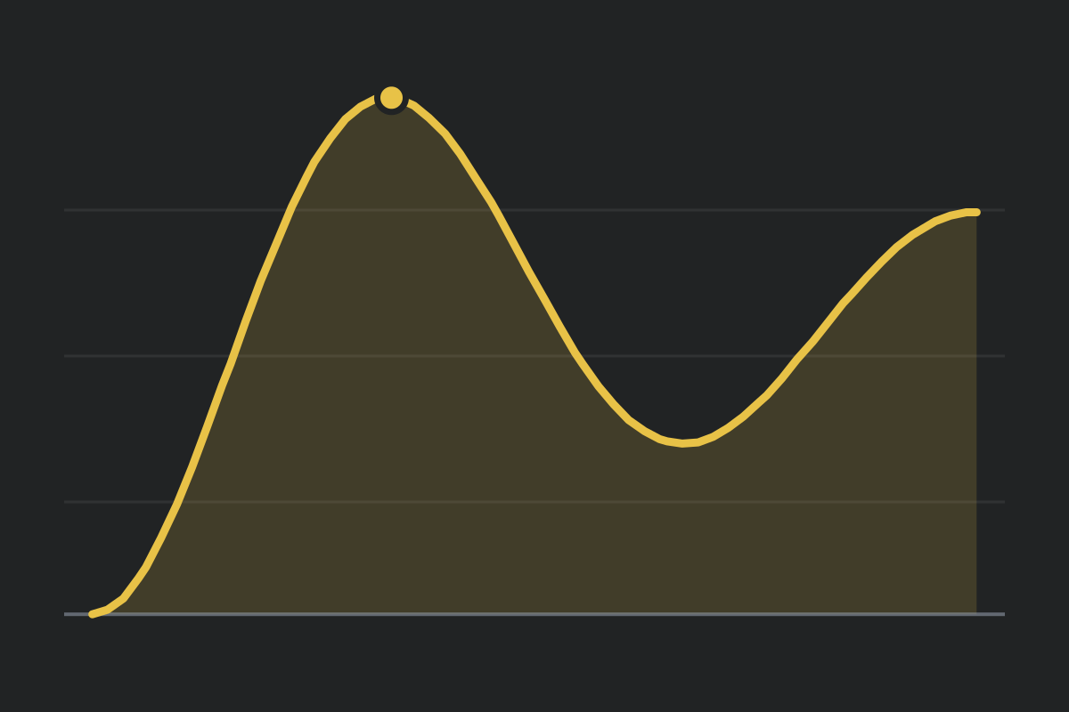
Charge the capacitor through a resistor alone and its voltage climbs to the supply and stops. Add an inductor and it sails past. The reason is that an inductor resists any change in current, so when the capacitor reaches the supply voltage the current does not obligingly stop. It keeps flowing, keeps delivering charge, and drives the voltage above the supply until the capacitor’s excess over the supply, which reverses the voltage across the inductor, finally turns it around.
The size of the overshoot is exp(−πζ/√(1−ζ²)), which depends on the damping ratio
and nothing else. At ζ = 0.1 it is 73 percent, at 0.5 it is 16 percent, and at 1 it is zero.
That is a real hazard rather than a curiosity: a 5 V logic supply that overshoots to 8.6 V on
power-up can destroy whatever it is feeding.
The current starts at zero, not at V over R
This surprises people who have only met RC circuits. In an RC circuit the current jumps
instantly to V/R at the moment of switching. Here it starts at exactly zero,
because a step change in current through an inductor would need an infinite voltage across it.
Watch the labels at the instant the switch closes: the entire supply voltage sits across the inductor, and none across the resistor, because no current is flowing yet. That is what makes the inductor the component setting the initial behaviour.
What critical damping is for
The critical resistance is 2√(L/C), and it separates two qualitatively different
behaviours.
- Below it. The circuit rings at
f₀√(1 − ζ²)and overshoots, and well below it takes a while to settle down. - At it. The fastest possible approach to the final voltage with no overshoot at all, which is what an instrument or a control loop needs wherever any overshoot is a false reading. It is not the fastest to settle: at ζ around 0.8 the circuit overshoots by about 1.5 percent but settles within 2 percent of the supply sooner.
- Above it. No overshoot, but slower, and getting slower the more resistance you add. Past critical, more damping is worse, not safer.
Set the resistance to the critical value shown in the readouts and watch the last of the ringing vanish. Then push it to three times critical and watch the settling time grow.
Where the energy goes
The bar under the schematic shows how the stored energy splits between the capacitor’s electric field and the inductor’s magnetic field. Set the resistance to zero and the split sloshes back and forth indefinitely, exactly as kinetic and potential energy do in an undamped spring. The resistor is the only component that removes energy from the circuit; it turns it into heat, which is why the ringing dies away.
What this model leaves out
Ideal components. Real inductors have winding resistance, often tens of ohms, which adds to whatever R you set and damps the circuit more than you asked for; that alone explains many circuits that ring less than predicted. Real capacitors have series resistance and leak. Neither is included here.
The supply is also ideal, with no internal resistance and an instantaneous switch. And everything is linear: no component saturates, and the inductor’s inductance never falls as the current rises, which a real ferrite core does.
Common mistakes
- Expecting the capacitor to stop at the supply voltage. Only if the resistance is at or above critical.
- Using the resonant frequency as the ringing frequency. The circuit rings
at
f₀√(1 − ζ²), which is lower, and does not ring at all past critical. - Thinking more resistance always settles things faster. Broadly true well below critical, but the quickest settling comes a little under it, at ζ around 0.8, and past critical more resistance only slows it.
- Forgetting the inductor’s own resistance. It adds to R, and for a small inductor it can dominate whatever resistor you fitted.
- Mixing prefixes. Millihenries with microfarads, or henries with
nanofarads, throws
√(LC)out by a factor of a thousand or more. The sliders here are in mH and nF and the conversion is done for you. - Assuming no current means no stored energy. At the peak of the overshoot the current is zero, so the inductor stores nothing, yet the capacitor holds more energy than it will once the circuit has settled.
Model and assumptions
- Method
- Runge-Kutta 4th order
- Largest step
- 0.000002 s
- Repeatability
- Deterministic. The same link gives the same numbers on any machine.
What it assumes
- Ideal lumped components: resistance, inductance and capacitance are constant and none of them varies with current, voltage or frequency.
- State is charge and current, so capacitor voltage is charge over capacitance wherever it is displayed.
- The supply is ideal with no source resistance, and the switch closes instantly at time zero.
Where it stops holding. Inductance approaching zero, where the equation stops being second order. The model enforces a floor rather than dividing by zero.
Numerical accuracy
- Estimated error
- 1.6e-6 V in the capacitor voltage, about 2.0e-7 of the largest value reached
- How that was obtained
- Running the same problem again at half the step changed the answer by at most 1.5e-6 V over 400 us, about two ringing cycles. Richardson extrapolation of that difference gives the figure above.
- Observed order
- 4.01, measured from a second halving rather than assumed
- Conditions
- 100 ohm, 10 mH, 100 nF, 5 V step, the shipped defaults
Common questions
Why does the capacitor voltage go above the supply?
Because the inductor keeps the current flowing after the capacitor has reached the supply voltage. An inductor resists any change in current, so when the capacitor is full the current does not stop; it keeps delivering charge and pushes the voltage past the supply. The overshoot is exp(−πζ/√(1−ζ²)), which depends only on the damping ratio, and it disappears entirely once the resistance reaches 2√(L/C).
What is critical damping in a circuit for?
It is the fastest the circuit can reach its final voltage without ever overshooting it. That is what you want in a measuring instrument or a control loop where any overshoot is a false reading and a slow approach wastes time. It is not quite the fastest to settle, though: slightly below critical, with ζ around 0.8, the voltage overshoots by about 1.5 percent but settles to within 2 percent of the supply sooner than a critically damped circuit does. Well below critical the circuit rings and takes longer to settle; above it the circuit never overshoots but crawls, so more resistance past critical makes things worse rather than better.
Why does the current start at zero rather than at V over R?
Because of the inductor. A step change in current would need an infinite voltage across it, since the voltage is L times the rate of change, so the current has to start from zero and build. At the instant the switch closes the entire supply voltage appears across the inductor and none of it across the resistor. In a pure RC circuit with no inductance the current does jump straight to V/R.
Is this the same mathematics as a mass on a spring?
Yes, exactly. Inductance plays the role of mass, resistance of the damping coefficient, and one over capacitance of the spring constant, so both obey the same second-order equation and both have the same three damping regimes at the same boundary. Comparing this with the mass spring simulator is the quickest way to see that a single piece of mathematics describes two things that look nothing alike.