Electromagnetic Induction Simulator
Electromagnetic induction simulation: move a magnet through a coil and watch Faraday’s law, EMF = −N dΦ/dt, swing a galvanometer, with Lenz’s law shown.
Simulator
Drag the magnet along the axis, or use the left and right arrow keys, Home and End, to move it by hand. Space plays and pauses.
- Peak EMF Half a radius from the coil, at 1.5 cm, not in its plane.
- 119.9 mV
- EMF now
- 0 mV
- Current now The EMF over the circuit resistance.
- 0 mA
- Flux linkage now N times the flux through one turn. Largest with the magnet in the coil, where the EMF is zero.
- 0.0994 mWb
- Coil face towards magnet The pole the induced current makes of the coil’s face nearer the magnet. It always opposes the motion.
- none
- Opposing force now The push the induced current gives the magnet, always against its velocity.
- 0 µN
- Charge on the way in N times the change in flux, over R. The same at any speed.
- 81.79 µC
- Flux linkage NΦ
- EMF
Citing this tool
Last updated . Add the date you accessed it as well, which a citation of a page that can change asks for. If a specific result matters, cite the permalink from the tool’s share row instead of this page: it reproduces the exact parameters.
The equation
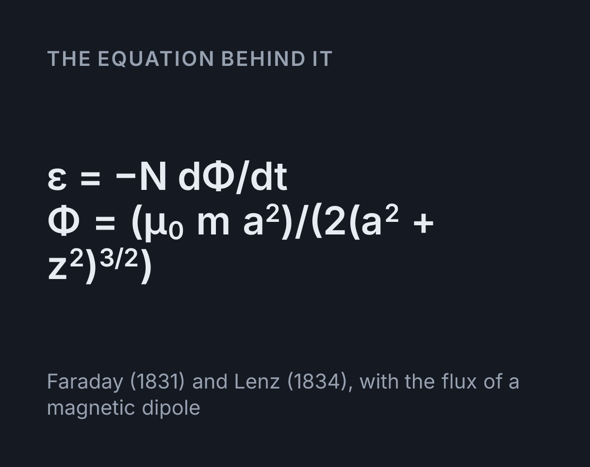
Faraday (1831) and Lenz (1834), with the flux of a magnetic dipole
What electromagnetic induction is
Electromagnetic induction is the production of an EMF in a circuit by a changing magnetic
flux through it.
Faraday’s law gives its size, ε = −N dΦ/dt, for a coil of N turns each linking a
flux Φ, and Lenz’s law gives its direction: the current always flows the way that opposes the
change that made it.
This simulation moves a bar magnet along the axis of a coil and computes both, exactly, for a
magnet treated as a point magnetic dipole of moment m. With the magnet a distance z from a turn
of radius a, the flux through that turn is
Φ = μ₀ m a² / (2(a² + z²)^(3/2)), where μ₀ is the
vacuum permeability. The flux changes only
because the magnet moves, so the EMF is −N (dΦ/dz) v for a magnet moving at speed
v, and the current through the galvanometer is that EMF over the circuit resistance.
How to use the simulation
Press Play and the magnet passes through the coil at a steady speed, in slow motion so the needle can be followed. Choose Oscillate to swing it back and forth through the coil, as a magnet on a spring would, or drag it yourself: grab the magnet, or focus the scene and use the arrow keys, Home and End. Flip the magnet to reverse every reading.
- Peak EMF is the largest EMF over a run, and it sets the galvanometer’s full scale.
- Flux linkage is N times the flux through one turn, NΦ, in webers. The top plot shows it; the EMF in the plot below is minus its rate of change.
- Coil face towards magnet is the pole the induced current turns the coil’s nearer face into. It is the magnet’s leading pole as it approaches and the opposite of its trailing pole as it leaves: repelling on the way in, attracting on the way out.
- Charge on the way in is the charge that flows round the circuit while the magnet comes from the end of its travel to the coil.
Worked example: a magnet pushed through a 200-turn coil
Take the opening settings: 200 turns of radius 3 cm, a magnet of moment 1 A m² moving at 1 m/s from 10 cm on one side to 10 cm on the other, and 50 Ω in the circuit.
- With the magnet in the plane of the coil, each turn links μ₀m/(2a), so the flux linkage is 200 × μ₀ × 1 / 0.06, or 4.189 mWb. At 10 cm away it is only 0.0994 mWb, so the linkage rises by 4.089 mWb on the way in.
- The EMF peaks where the flux is changing fastest, half a radius from the coil at 1.5 cm, not in its plane. There it is (3/4)(4/5)^(5/2) × Nμ₀mv/a², which is 119.9 mV, driving 2.398 mA through the 50 Ω, a little under half of the dial’s 5 mA full scale.
- The approach takes 0.1 s, so the average EMF on the way in is 4.089 mWb / 0.1 s = 40.89 mV, and the charge that flows is 4.089 mWb / 50 Ω = 81.79 µC.
- At the peak the induced current pushes back on the magnet with a force of EMF² / (Rv) = 0.2875 mN, the force whose work becomes the heat in the circuit.
- Double the speed to 2 m/s and the peak doubles to 239.8 mV while the pulse lasts half as long, so the charge on the way in is still 81.79 µC.
Set the magnet to oscillate with the same 1 m/s peak speed and the peak EMF falls slightly, to 118.6 mV, because 1.5 cm from the coil the magnet is still a little short of its peak speed, which it reaches only in the coil’s plane.
Lenz’s law: which way the current goes
The induced current makes the coil a magnet of its own, and its poles always oppose the motion. Push a north pole towards the coil and the nearer face becomes a north pole, pushing back. Pull the magnet away and its south end, now facing the coil, meets a north face that holds it back. Either way you do work against the coil, and that work is exactly the heat the current makes in the circuit, which is where the energy of the electricity comes from.
If the current flowed the other way, the coil would pull the magnet in faster, which would drive a larger current, which would pull harder still: energy from nothing. Lenz’s law is the minus sign in Faraday’s law, and conservation of energy is why it is there.
Why the EMF is zero with the magnet in the middle
With the magnet in the coil’s plane the flux linkage is at its largest, and for that instant it is not changing, so the EMF is zero and the needle swings through the centre of the dial. The EMF depends on the rate of change of flux, not on the flux. That is why a pass gives two pulses of opposite sign, one on the way in and one on the way out, and why a magnet held still inside a coil gives nothing at all.
Faster magnet, same charge
Moving the magnet faster raises the EMF in proportion, but the area under the EMF curve on the way in is always N times the change in flux, whatever the speed. The charge that flows is that area over the resistance, so it does not depend on speed either. On the way out the same charge flows back, and a complete pass moves no net charge round the circuit, even though it has turned energy into heat. That heat does grow with speed, because the power in the circuit goes as the EMF squared.
The same reasoning explains the other controls. The EMF is proportional to the number of turns and the strength of the magnet. A wider coil links less flux at the centre, μ₀m/(2a) per turn, and spreads the change over a longer distance, so the peak EMF falls as one over the radius squared. The resistance sets the current and the force on the magnet, not the EMF. To see how the current relates to the EMF in a circuit, try the Ohm’s law calculator; for how the resistance of the coil’s own wire depends on its length and thickness, the wire resistance calculator.
What this does not cover
- A real bar magnet has length. The model’s magnet is a point dipole, which holds when the magnet is small compared with the coil’s radius and its distance from the coil. A magnet as long as the coil is wide, passing through it, gives a lower and broader pulse than the one shown.
- The coil is flat. Every turn is treated as lying in one plane, which is fair for a coil much shorter than its radius. A long coil spreads its turns along the axis, and each one then sees the magnet at a different distance. The solenoid magnetic field simulator shows the field of such a coil.
- The coil’s own inductance is ignored, so the current follows the EMF instantly. With many turns and a small resistance, the coil’s inductance over the resistance can become comparable with the time the magnet takes to cross it, and then the current lags and is smaller. The RLC circuit simulator shows what an inductor does to a current.
- The magnet is not slowed. Its motion is imposed, so the opposing force is reported but does not act on it. A magnet dropped through a closed coil really is slowed by it.
Common mistakes
- Expecting the largest EMF with the magnet inside the coil. That is where the flux is largest and the EMF is zero. The peak is half a radius away.
- Forgetting the minus sign. It is Lenz’s law, and it decides which way the needle swings.
- Getting the pole the wrong way round on the way out. The coil attracts a leaving magnet, so its face is the opposite of the magnet’s nearer, trailing pole.
- Thinking a stronger push moves more charge. It gives a larger EMF for a shorter time. The charge depends only on the change in flux linkage and the resistance.
- Using flux where flux linkage is meant. Faraday’s law for a coil multiplies the flux through one turn by the number of turns.
The laws are Faraday’s, from his experiments of 1831, and Lenz’s, from 1834. The flux of a dipole through a loop follows from the on-axis field of a current loop, as in Griffiths, Introduction to Electrodynamics, example 5.6.
Model and assumptions
- Method
- Exact expression, no time stepping
- Repeatability
- Deterministic. The same link gives the same numbers on any machine.
What it assumes
- The magnet is a point magnetic dipole on the coil’s axis, so the flux through each turn is exactly μ₀ma²/(2(a² + z²)^(3/2)) and the EMF is minus N times its rate of change.
- Every turn of the coil lies in one plane, which holds for a coil much shorter than its radius.
- The coil’s self-inductance is neglected, so the current is the EMF over the circuit resistance at every instant.
- The magnet’s motion is imposed, so the opposing force Lenz’s law predicts is reported but does not slow it.
Where it stops holding. Close to the coil for a real bar magnet, which is not a point: a magnet whose length is comparable with the coil’s radius gives a lower, broader pulse than a dipole of the same moment. The current also lags the EMF and falls short of it once the coil’s inductance over the circuit resistance is not small compared with the time the magnet takes to cross the coil, which is soonest with many turns and a small resistance.
Numerical accuracy
No time stepping, so nothing accumulates: the flux, the EMF, the current, the opposing force and both peaks are closed forms in the magnet’s position and speed, exact to rounding for the pass and the oscillation. The one estimate is the speed of a magnet dragged by hand, which is the pointer’s movement averaged over about a twentieth of a second, so while you drag, the EMF follows your hand with that short lag.
Common questions
What is electromagnetic induction?
The production of an EMF in a circuit by a changing magnetic flux through it. Faraday’s law gives its size as ε = −N dΦ/dt, the number of turns times the rate at which the flux through each turn changes, and Lenz’s law gives its direction: the induced current always flows so as to oppose the change that caused it. Moving a magnet into a coil, moving a coil past a magnet and switching a current on in a nearby coil all do it, because each changes the flux. A magnet held still inside a coil does nothing, however strong it is.
Why is the EMF zero when the magnet is in the middle of the coil?
Because the flux is not changing at that instant. With the magnet in the coil’s plane the flux linkage is at its largest, so for a moment it neither rises nor falls, and the EMF, which depends on the rate of change of flux and not on the flux itself, passes through zero. That is why a magnet pushed right through a coil gives two pulses of opposite sign, one on the way in and one on the way out, and why the galvanometer swings one way and then the other.
Where is the induced EMF largest?
Half a coil radius from the coil, for a small magnet moving along the axis at steady speed. The flux through a turn goes as 1/(a² + z²)^(3/2), and its rate of change with position is steepest at z = a/2, so the peak EMF is (3/4)(4/5)^(5/2) Nμ₀mv/a², about 0.43 Nμ₀mv/a². With 200 turns of radius 3 cm and a magnet of moment 1 A m² at 1 m/s, as the simulator opens, that is 119.9 mV at 1.5 cm from the coil.
Which way does the induced current flow, by Lenz’s law?
Whichever way makes the coil oppose the magnet’s motion. As a north pole approaches, the current turns the coil’s nearer face into a north pole, which repels it. As the magnet leaves, its south end faces the coil and the current reverses, making that face a north pole that attracts it back. The work done against that opposition is exactly the energy that appears as heat in the circuit, which is why the current cannot flow the other way: that would pull the magnet in faster and create energy from nothing.
Does moving the magnet faster push more charge round the circuit?
No. A faster magnet gives a proportionally larger EMF for a proportionally shorter time, and the charge that flows while it comes in is N times the change in flux divided by the resistance, with no speed in it at all. At the simulator’s opening settings that is 81.79 µC at any speed, and the same charge flows back as the magnet leaves. What does grow with speed is the heat, because the power in the circuit goes as the EMF squared.