Resistor Network Calculator
Total resistance for resistors in series, in parallel, or parallel groups in series, with the current, voltage and power in each resistor from one supply.
Calculator
Total resistance Ω
Total current mA
The supply delivers 324.2 mW, which is what every resistor’s power adds up to.
| Stage | R | V | I | P | Share of I |
|---|---|---|---|---|---|
| 1 | 100 Ω | 3.602 V | 36.02 mA | 129.8 mW | 100% |
| 2 (parallel 1) | 220 Ω | 5.398 V | 24.54 mA | 132.4 mW | 68.1% |
| 2 (parallel 2) | 470 Ω | 5.398 V | 11.48 mA | 61.99 mW | 31.9% |
Working, stage by stage
- Stage 1 is a single resistor of 100 Ω.
- Stage 2 is 220 Ω and 470 Ω in parallel.
- R2 = 1 / (1/220 + 1/470) = 149.86 Ω
- That is below 220 Ω, the smallest of them, as a parallel combination always is.
- R total = 100 + 149.86 = 249.86 Ω
- I total = 9 / 249.86 = 0.036021 A
- V across stage 1 = 0.036021 x 100 = 3.6021 V
- V across stage 2 = 0.036021 x 149.86 = 5.3979 V
- I through 220 Ω = 5.3979 / 220 = 0.024536 A
- I through 470 Ω = 5.3979 / 470 = 0.011485 A
In series every resistor carries the same current and drops its own voltage. In parallel every resistor sees the same voltage and takes its own current, so the smallest one takes the most. Those two sentences are the whole of it.
Citing this tool
Last updated . Add the date you accessed it as well, which a citation of a page that can change asks for. If a specific result matters, cite the permalink from the tool’s share row instead of this page: it reproduces the exact parameters.
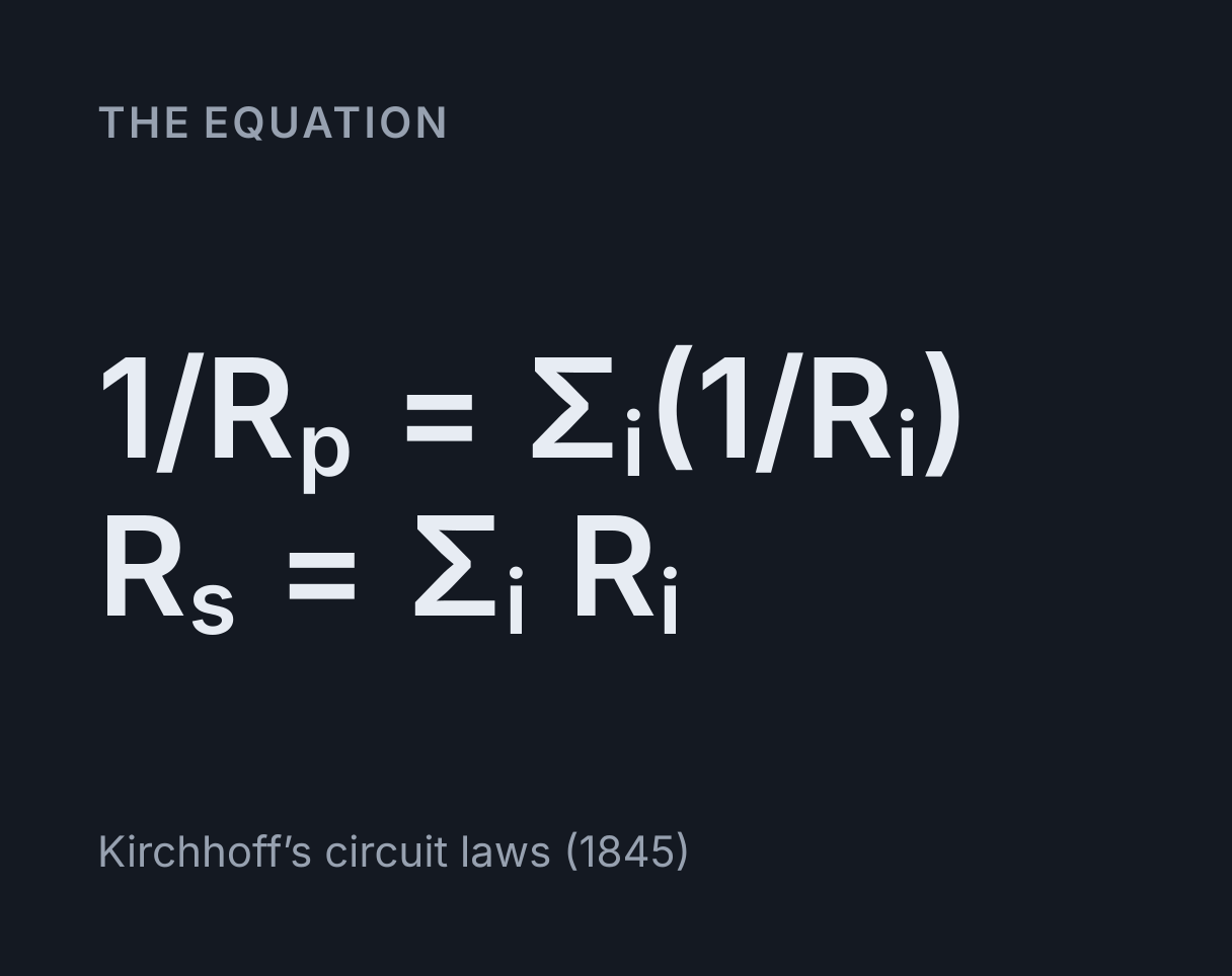
The equation
Kirchhoff’s circuit laws (1845)
Two rules, and one of them is counterintuitive
Resistors in series add, R = R₁ + R₂ + R₃, and resistors in parallel add
as reciprocals, 1/R = 1/R₁ + 1/R₂ + 1/R₃. In series every resistor
carries the same current, because there is nowhere else for it to go, and each one
drops a share of the voltage in proportion to its resistance.
In parallel every resistor sees the same voltage, because both ends are connected to the same two points, and each one takes a current in inverse proportion to its resistance. The smallest resistor takes the most current, which is the opposite of what the series case teaches.
Worked example: 100 Ω feeding 220 Ω and 470 Ω
The parallel pair first.
1/220 + 1/470 = 0.00454545 + 0.00212766 = 0.00667311, and the
reciprocal of that is 149.855 Ω. Note it is below 220, the smaller of the two, as a
parallel combination always is. Adding the 100 Ω in series gives 249.855 Ω in
total.
On a 9 V supply the total current is 9 / 249.855 = 36.021 mA, and that
current flows through the 100 Ω resistor, dropping 3.6021 V across it.
The remaining 5.3979 V appears across the parallel pair, so the 220 Ω
takes 5.3979 / 220 = 24.54 mA and the 470 Ω takes
5.3979 / 470 = 11.48 mA, the figures the table shows. Those two add back
to 36.02 mA, which is the check worth doing.
Shortcuts that are worth knowing
Two equal resistors in parallel give half the value, and n equal resistors give
R/n. Two unequal ones are R₁R₂ / (R₁ + R₂), the product over the sum,
which is quicker by hand than three reciprocals but only works for exactly two.
Extending it to three by multiplying and adding all three is a common and completely
wrong move.
A very large resistor in parallel with a small one is almost irrelevant: 1 MΩ across 100 Ω gives 99.99 Ω. A very small one dominates completely. That is why a short circuit across part of a network removes it from the calculation, and why a broken resistor in a parallel group changes the total much less than one in series.
Voltage dividers and current dividers
A series pair is a voltage divider: the voltage across R₂ is
V × R₂ / (R₁ + R₂). That is not a separate formula, it is what the
series rules already say, which is why this calculator gives it without a separate
mode. Loading the output with anything comparable to R₂ changes the answer, and the
way to model that is to put the load in parallel with R₂ inside the same stage. To
work a two-resistor divider backwards, finding the R₂ that gives a target output, or
to see its output resistance and loaded output directly, use the
voltage divider calculator.
A parallel pair is a current divider: the current through R₁ is
I × R₂ / (R₁ + R₂), with the other resistor’s value on top. The
crossover is the part people get wrong when they write it from memory, and it is
exactly the inverse proportionality the table above shows directly.
Power, and why per-resistor figures matter
Each resistor dissipates I²R, using its own current. In a parallel group
those currents differ, so the powers differ, and the smallest resistor is doing the
most work. A quarter-watt part asked for 0.4 W will discolour, drift upwards in value
and eventually fail open, usually months later.
The individual powers always sum to V × I at the supply, which is another
arithmetic check the table makes available. If your figures do not add up, a current
is wrong somewhere.
What this does not cover
The network here is a series chain in which any link can be a parallel group. That covers almost every question that gets asked, and it deliberately excludes networks that are not reducible that way, the Wheatstone bridge being the standard example. Those need nodal analysis, and describing one needs a schematic editor rather than a list.
Everything assumes ideal resistors and an ideal supply: no tolerance, no temperature coefficient, no source resistance. Real parts are typically 1 or 5 percent, so quoting a total to five figures is arithmetic rather than accuracy. If the supply has meaningful internal resistance, add it as a first series stage.
Common mistakes
- Forgetting the final reciprocal. Adding
1/220 + 1/470gives 0.00667311, which is not the answer. The answer is one over that. - Using product over sum for three resistors. It only holds for two.
- Assuming the biggest resistor always carries the most. True for voltage in series, false for current in parallel.
- Mixing units. A resistance in kΩ with a voltage in volts gives a current in milliamps, not amps. Everything here is in ohms, volts and amps, and the display switches to mA or µA only for readability.
- Ignoring the load on a divider. An unloaded divider and a loaded one give different outputs. Put the load in the same stage as the lower resistor.
- Sizing every resistor by the total power. Each part only has to survive its own dissipation, and in a parallel group that is unevenly shared.
Common questions
Why is a parallel combination smaller than the smallest resistor?
Because adding a parallel path adds somewhere else for current to go, and more current for the same voltage means less resistance. Two 100 Ω resistors in parallel give 50 Ω, and adding a 1 MΩ resistor across a 4.7 Ω one still leaves under 4.7 Ω. That is the check to apply to any parallel answer: if it is not below the smallest member you have probably forgotten the final reciprocal.
Which resistor carries the most current?
In series, all of them carry the same current and the largest resistor drops the most voltage. In parallel, all of them see the same voltage and the smallest resistor takes the most current. The second one catches people out because it is the opposite of the series intuition, so this calculator shows the current in every individual resistor rather than only the total.
How do I enter a mixed network?
Stages run in series down the page, and putting two or more resistors inside one stage makes them parallel with each other. So 100 Ω feeding a parallel pair of 220 Ω and 470 Ω is two stages: one resistor in the first, two in the second. Anything that is not a series chain of parallel groups, a bridge circuit for example, needs nodal analysis and is outside what this does.
Why does the power matter?
Because a resistor’s power rating is what decides whether it survives. A quarter-watt part dissipating 0.4 W will discolour, drift and eventually fail, and the current through it in a parallel group can be far higher than the average. The table gives the power in each resistor separately for that reason, and the individual figures always add up to the supply’s output.