LED Resistor Calculator
Find the series resistor for any LED from supply voltage, forward voltage and current, with the next E12 part up and power dissipation.
Calculator
Red ~1.8, yellow ~2.1, green ~2.2, blue and white ~3.2.
20 mA is typical for a 5 mm indicator LED. Check the datasheet.
Working, with your numbers
- R = (Vs - Vf) / I
- headroom = 5 - 2 = 3 V
- = 3 / 0.02 A
- = 150 ohm
Values are converted into the units the equation is worked in before the arithmetic.
- Next E12 part up Rounded up, since a larger resistor keeps current under the rating.
- 150 Ω
- Actual current
- 20 mA
- Resistor power P = I²R. A standard 1/4 W part handles 250 mW.
- 60 mW
- LED power
- 40 mW
Citing this tool
Last updated . Add the date you accessed it as well, which a citation of a page that can change asks for. If a specific result matters, cite the permalink from the tool’s share row instead of this page: it reproduces the exact parameters.
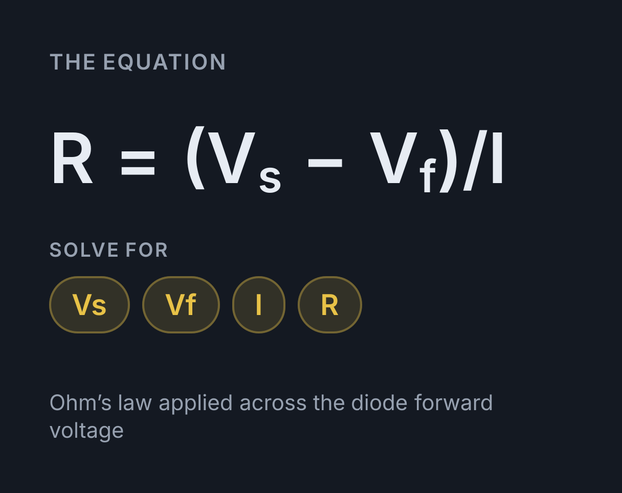
The equation
Ohm’s law applied across the diode forward voltage
Why an LED needs a series resistor
The series resistor for an LED is R = (Vs − Vf) / I: the
supply voltage minus the LED’s forward voltage, divided by the current you
want through it. An LED is a diode, not a resistor. Below its forward
voltage almost no current passes; above it the current rises very steeply
for a small increase in voltage. A tenth of a volt past the knee can double
the current. Connected straight across a supply, the LED therefore draws
whatever that supply can deliver, heats up, drops its forward voltage
slightly as it does so, and draws more still. The usual outcome is a dead
part in under a second.
A series resistor turns the circuit into something predictable, because it
takes up the difference between the supply and the forward voltage and
sets the current by Ohm’s law: R = (Vs - Vf) / I. Forward
voltage depends on the semiconductor, so it varies by colour. Typical
figures are red about 1.8 V, yellow about 2.1 V, green
about 2.2 V, and blue or white about 3.2 V. Most indicator LEDs are rated
for 20 mA, and many are perfectly visible at 5 mA.
Worked example
A red LED with Vf = 2 V is to run at 20 mA from a 5 V supply.
- Voltage across the resistor:
5 - 2 = 3 V R = 3 V / 0.02 A = 150 Ω-
Power in the resistor:
P = I²R = 0.02² × 150 = 0.06 W = 60 mW - A common quarter-watt resistor is rated for 250 mW, so 60 mW leaves ample margin.
150 Ω happens to be a standard value. Where the calculated figure is not, the safe direction is clear.
Choosing the actual part
Round the calculated resistance up to the next standard E12 value. A larger resistor passes slightly less current and gives a slightly dimmer LED, which is harmless; a smaller one pushes the current past the rating and shortens the life of the part. If the calculation returned 165 Ω, fit 180 Ω rather than 150 Ω.
Headroom deserves a check as well. When Vs - Vf is small, say
under about 0.5 V, the resistor is doing very little and the current
becomes highly sensitive to the forward voltage of the individual LED,
which varies from part to part and drifts with temperature. Two LEDs from
the same bag can then differ visibly in brightness. Driving a 3.2 V white
LED from a 3.3 V rail is the classic example, and it is better solved with
a constant-current driver than with a resistor.
Common mistakes
- Omitting the resistor. Bare LEDs across a supply survive only by luck, usually because the supply itself is current limited.
- Supply below the forward voltage. A 3 V cell cannot drive a 3.2 V blue LED at its rated current, and no choice of resistor changes that, since a resistor can only take voltage away. The supply has to be raised.
- Several LEDs in parallel behind one resistor. The one with the lowest forward voltage takes most of the current and the rest stay dim. Give each LED its own resistor, or wire them in series with a single resistor.
- Ignoring the resistor power rating. Indicator currents are trivial, but at 350 mA through a 3 Ω resistor the dissipation is 0.37 W and a quarter-watt part will run hot.
Converting units first? Use the resistance, electric current and voltage conversion tables.
Worked examples
Each one runs through the calculator above, so the arithmetic here is the arithmetic it does.
What resistor does a red LED need at 20 mA on a 12 V supply?
- R = (Vs - Vf) / I
- headroom = 12 - 1.8 = 10.2 V
- = 10.2 / 0.02 A
- = 510 ohm
510 Ω, which rounds up to the 560 Ω E12 part and about 18 mA. The resistor drops 10.2 of the 12 volts and dissipates about 0.2 W against the LED’s 36 mW, most of a quarter-watt rating, so two or three LEDs in series on one resistor put that voltage to use instead of turning it into heat.
How much current does a 330 Ω resistor let through a blue LED on 5 V?
- I = (Vs - Vf) / R
- headroom = 5 - 3.2 = 1.8 V
- = 1.8 / 330
- = 0.005455 A = 5.455 mA
About 5.5 mA, a quarter of the usual 20 mA, because a blue LED’s 3.2 V forward drop leaves only 1.8 V across the resistor. The same resistor passes about 9.7 mA through a red LED on this supply, so a value copied from a red LED circuit leaves a blue one noticeably dim.
Practise this with Electricity Practice Problems, questions generated from this calculator and 6 other calculators in Electricity.
Common questions
Why does an LED need a resistor at all?
An LED’s current rises almost vertically once it passes its forward voltage, so a small increase in supply voltage produces a very large increase in current. Without a series resistor to set that current, the LED draws whatever the supply can deliver and destroys itself.
Should I round the resistor up or down?
Up. A larger resistor means slightly less current and a marginally dimmer LED, while a smaller one pushes current above the rating and shortens its life. This calculator suggests the next E12 value at or above the computed figure, and shows the current you would actually get.