Voltage Divider Calculator
The voltage divider formula is Vout = Vin × R₂/(R₁ + R₂). Solve for the output, the input, R₁ or R₂, with the current, power and loaded output shown.
Calculator
Across R₂, with nothing connected to the output. The load readout shows what a load does to it.
Between the input and the output.
Between the output and 0 V. The output is taken across it.
What the output feeds. A basic digital voltmeter is about 10 MΩ. Only the load readout and the warning use it.
Working, with your numbers
- Vout = Vin x R2 / (R1 + R2)
- = 5 V x 15 kohm / (10 kohm + 15 kohm)
- = 5 V x 15 / 25
- = 3 V
Values are converted into the units the equation is worked in before the arithmetic.
- Divider current I = Vin ÷ (R₁ + R₂). With nothing connected to the output, the same current flows through both resistors.
- 200 µA
- Division ratio Vout ÷ Vin, which is R₂ ÷ (R₁ + R₂). Divide a measured output by it to get back the input.
- 0.6
- Voltage across R₁ Vin − Vout. The supply splits in the ratio of the resistors, V₁ ÷ V₂ = R₁ ÷ R₂.
- 2 V
- Power in R₁ I²R₁. A common quarter-watt resistor is rated for 0.25 W, so choose a part rated for about twice the figure.
- 400 µW
- Power in R₂ I²R₂. Scaling both resistors up by the same factor keeps the output and divides every power by that factor.
- 600 µW
- Output resistance R₁ and R₂ in parallel, R₁R₂ ÷ (R₁ + R₂). To a load, the divider looks like the unloaded Vout behind this resistance.
- 6 kΩ
- Output with the load Vout × RL ÷ (RL + Rout), Rout being the output resistance, with the load connected across R₂. It stays within 1 percent of Vout while RL is at least 99 times Rout.
- 2.998 V
Citing this tool
Last updated . Add the date you accessed it as well, which a citation of a page that can change asks for. If a specific result matters, cite the permalink from the tool’s share row instead of this page: it reproduces the exact parameters.
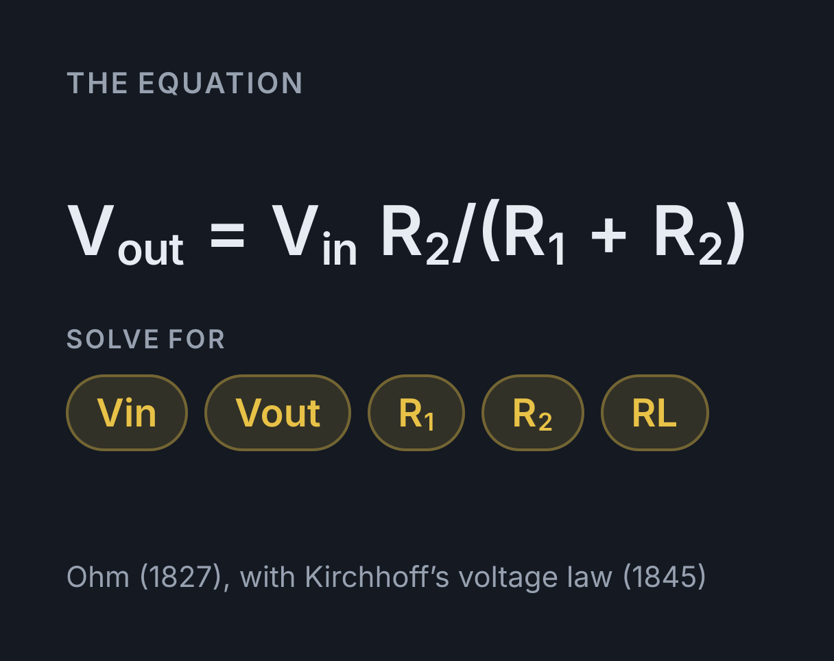
The equation
Ohm (1827), with Kirchhoff’s voltage law (1845)
The voltage divider formula
A voltage divider is two resistors in series across a supply, with the
output taken across the lower one, and its output is
Vout = Vin × R₂ / (R₁ + R₂): the output is the same fraction
of the input as R₂ is of the total resistance. R₁ sits between the input
and the output, R₂ between the output and 0 V. For the values loaded
above, 5 V across 10 kΩ and 15 kΩ,
Vout = 5 × 15 ÷ (10 + 15) = 3 V, three fifths of the supply.
Enter any three of the input voltage, the output voltage, R₁ and R₂, and choose Solve for this on the fourth. Solving for R₂ answers the question most divider designs start with, which resistor gives this output, and solving for the input reads a supply back from a measured output. Beside the answer the calculator shows the current through the divider, the division ratio Vout ÷ Vin, the voltage across R₁, the power in each resistor, the output resistance, and the output with a load connected. The load starts at 10 MΩ, about what a basic digital voltmeter presents, so the page opens on what a meter across R₂ would read. Every figure except that last one describes the divider with nothing connected to its output.
Why the supply divides in the ratio of the resistors
With nothing drawing on the output, one current flows through both
resistors, and in series their resistances add. By Ohm’s law that current
is I = Vin / (R₁ + R₂), and the voltage across R₂ is
I × R₂, which is the formula above. Kirchhoff’s voltage law
closes the loop: the two drops, I × R₁ and
I × R₂, add up to the supply. For the values above the
current is 5 V ÷ 25 kΩ = 200 µA, R₁ drops 2 V and R₂ the remaining 3 V.
The Ohm’s law calculator works
each of those drops on its own.
The same current in both resistors also gives the second form that
OCR’s A level formula booklet prints beside the first,
V₁ / V₂ = R₁ / R₂: each resistor takes a share of the supply
in proportion to its resistance. Only the ratio matters, so 1 kΩ over
1.5 kΩ and 100 kΩ over 150 kΩ give the same 3 V from 5 V. What the size
of the resistors decides is how much current the divider wastes and how
well it copes with a load.
Worked example: a 9 V battery divider, with and without a load
Two 10 kΩ resistors in series across a 9 V battery make a divider. Find its output, the current and power, and what happens when a 10 kΩ load is connected to it.
-
Vout = 9 V × 10 kΩ ÷ (10 kΩ + 10 kΩ) = 4.5 V, half the supply. -
The divider draws
9 V ÷ 20 kΩ = 450 µA, and each resistor dissipates(450 µA)² × 10 kΩ = 2.025 mW. -
Its output resistance is
10 kΩ × 10 kΩ ÷ (10 kΩ + 10 kΩ) = 5 kΩ. -
With the load connected:
4.5 V × 10 kΩ ÷ (10 kΩ + 5 kΩ) = 3 V, a third below the unloaded answer.
The same 3 V comes from treating the load as part of the circuit: in parallel with R₂, the lower half of the divider becomes 5 kΩ, and 9 V shared between 10 kΩ and 5 kΩ gives 3 V. A basic 10 MΩ voltmeter across the same output reads 4.498 V, only 0.05 percent low, which is why a meter reads a divider almost exactly while a real load may pull it well down. Enter 9 V, 10 kΩ and 10 kΩ above and the load readout shows 4.498 V at the starting 10 MΩ and 3 V with the load set to 10 kΩ, and the calculator warns that the load has moved the output.
Loading a divider: the output resistance decides
Seen from its output, a divider behaves like a source of the unloaded
Vout behind a resistance of R₁ and R₂ in parallel,
Rout = R₁ × R₂ / (R₁ + R₂), which is its Thévenin
equivalent. A load RL across the output therefore receives
VL = Vout × RL / (RL + Rout). The output stays within
1 percent of Vout only while the load is at least 99 times the output
resistance, and within 10 percent while it is at least 9 times. For the
two 10 kΩ resistors that means a load of 495 kΩ or more for 1 percent and
45 kΩ or more for 10 percent. The calculator warns once the load pulls
the output more than 1 percent below Vout.
Smaller resistors make a stiffer divider, at a price. Swap the two 10 kΩ resistors for 100 Ω ones and the output is still 4.5 V, and the same 10 kΩ load now leaves it at 4.48 V, only 0.5 percent low. But the divider draws 45 mA instead of 450 µA, and each resistor dissipates 0.2 W, most of a quarter-watt rating. Choosing a divider is choosing between those two: resistors small enough that the load barely matters, and large enough that the current and heat stay small.
Potential dividers with sensors
Potential divider is the name UK A level physics uses for the same circuit, and AQA’s course asks for it with variable resistors, thermistors and light-dependent resistors (LDRs). The resistance of a thermistor falls as its temperature rises, and the resistance of an LDR falls as the light on it gets brighter. Put either sensor in a divider with a fixed resistor and its output voltage follows the temperature or the light, so with the sensor as R₁ the output rises as it warms or brightens, and with the sensor as R₂ the output falls. Swapping the two resistors is how a circuit is made to switch on in the dark rather than the light. A potentiometer is a divider in one part: the wiper splits a single track into R₁ and R₂, and turning it sets the ratio.
What this calculator does not cover
Every resistor here is exact. Real parts carry a tolerance, and with ±5 percent resistors the 5 V divider the page opens on could give anywhere from about 2.88 V to 3.12 V, so a divider that has to set a precise threshold needs 1 percent parts or a trimming potentiometer. The supply is ideal too: a real source has internal resistance, which sits in series with R₁ and lowers the output.
The load is assumed to be a resistor. An LED, a motor or a transistor
has no single resistance, and an LED needs one series resistor rather
than a divider, which the
LED resistor calculator
sizes. A capacitor across R₂ turns the divider into a low-pass filter
whose time constant uses R₁ × R₂ / (R₁ + R₂) as its
resistance, which the
RC time constant calculator
takes from there. For more than two resistors, a load built from several
parts, or a current divider, use the
resistor network calculator,
which gives the current and voltage in every resistor of a series chain
of parallel groups.
Common mistakes
- Putting the wrong resistor on top of the fraction. The output is across R₂, so R₂ goes on top. For the values above, R₁ on top gives 5 × 10 ÷ 25 = 2 V, which is the voltage across R₁, not the output.
- Mixing kilohms and ohms. The ratio only cancels when both resistors are in the same unit: 10 kΩ with 15 Ω is a ratio of 10,000 to 15, not 10 to 15. The calculator converts each field, and its working prints both resistors in one unit.
- Forgetting the load. The formula is for a divider with nothing connected. Anything across the output that is not far larger than the output resistance pulls it down, which the load readout shows.
- Using a divider as a power supply. Its output changes whenever the load does, so it suits signals and reference voltages feeding high-resistance inputs, not circuits that draw real current.
- Ignoring the power. Small resistors on a high voltage
run hot. Each resistor dissipates
I²R, and the calculator warns when either goes past the 0.25 W of a quarter-watt part.
Converting units first? Use the resistance and voltage conversion tables.
Worked examples
Each one runs through the calculator above, so the arithmetic here is the arithmetic it does.
What resistor gives 3.3 V from a 5 V supply with 10 kΩ on top?
- R2 = R1 x Vout / (Vin - Vout)
- = 10 kohm x 3.3 V / (5 V - 3.3 V)
- = 10 kohm x 3.3 / 1.7
- = 19.412 kohm
About 19.4 kΩ, which is not a standard part. Its neighbours in the E12 series are 18 kΩ, giving 3.21 V, and 22 kΩ, giving 3.44 V, so a design either accepts one of those or makes the value from two parts in series: 18 kΩ plus 1.5 kΩ gives 3.31 V.
What input voltage puts 3 V across the 10 kΩ of a 30 kΩ and 10 kΩ divider?
- Vin = Vout x (R1 + R2) / R2
- = 3 V x (30 kohm + 10 kohm) / 10 kohm
- = 3 V x 40 / 10
- = 12 V
12 V, four times the output, because the division ratio is a quarter. This is how a 3.3 V analogue input reads a 12 V battery: multiply the reading by 4, so a full-scale 3.3 V means 13.2 V. The input has to be at least 742.5 kΩ, 99 times the 7.5 kΩ output resistance, for the reading to stay within 1 percent.
What does a 100 Ω over 220 Ω divider give from 12 V, and is it safe?
- Vout = Vin x R2 / (R1 + R2)
- = 12 V x 220 ohm / (100 ohm + 220 ohm)
- = 12 V x 220 / 320
- = 8.25 V
8.25 V, but the pair draws 37.5 mA and R₂ dissipates 0.31 W, past a quarter-watt rating, which the calculator warns about. Scaling both resistors up by 100, to 10 kΩ and 22 kΩ, gives the same 8.25 V from 0.375 mA, with 4.5 mW in the pair.
Practise this with Electricity Practice Problems, questions generated from this calculator and 6 other calculators in Electricity.
Common questions
What is the voltage divider formula?
Vout = Vin × R₂ ÷ (R₁ + R₂), where R₂ is the resistor between the output and 0 V and R₁ the one between the input and the output. For 5 V across 10 kΩ and 15 kΩ, Vout = 5 × 15 ÷ 25 = 3 V. It holds while nothing connected to the output draws current.
How do I choose the resistors for a voltage divider?
Fix one resistor and solve for the other with R₂ = R₁ × Vout ÷ (Vin − Vout). For 3.3 V from 5 V with R₁ = 10 kΩ, that is 10 × 3.3 ÷ 1.7 = 19.4 kΩ. Then set the size of the pair from the load: their output resistance, R₁ and R₂ in parallel, should be no more than about a hundredth of the load for 1 percent accuracy, while the current and power stay small.
What happens when you connect a load to a voltage divider?
The output falls, because the load sits in parallel with R₂ and draws its current through R₁. The divider behaves like its unloaded output behind a resistance of R₁ and R₂ in parallel, so two 10 kΩ resistors on 9 V give 4.5 V on their own, behind 5 kΩ, and 3 V with a 10 kΩ load. To stay within 1 percent of the unloaded output, the load has to be at least 99 times that output resistance.
Is a potential divider the same as a voltage divider?
Yes. Potential divider is the name UK A level physics uses for the same circuit. OCR’s formula booklet gives it as Vout = R₂ ÷ (R₁ + R₂) × Vin, together with V₁ ÷ V₂ = R₁ ÷ R₂, which says the supply splits in the ratio of the resistors, and AQA’s course uses it with thermistors and light-dependent resistors as sensors.
Can a voltage divider power a circuit?
Not well. Its output falls as soon as a load draws current and changes whenever the load does, so it suits signals and reference voltages feeding high-resistance inputs, not motors, LEDs or anything that draws real current. A supply for those needs a voltage regulator, which holds its output as the load changes.