Capacitors in Series and Parallel Calculator
Capacitors in parallel add, C = C₁ + C₂; in series, 1/C = 1/C₁ + 1/C₂. Get the equivalent capacitance and the charge and voltage on each capacitor.
Calculator
Equivalent capacitance µF
Charge from the supply µC
The network stores 288 µJ, which is what every capacitor’s energy adds up to.
| Stage | C | V | Q | Energy |
|---|---|---|---|---|
| 1 | 12 µF | 4 V | 48 µC | 96 µJ |
| 2 (parallel 1) | 2 µF | 8 V | 16 µC | 64 µJ |
| 2 (parallel 2) | 4 µF | 8 V | 32 µC | 128 µJ |
Working, stage by stage
- Stage 1 is a single capacitor of 12 µF.
- Stage 2 is 2 µF and 4 µF in parallel.
- C of stage 2 = 2 + 4 = 6 µF
- C total = 1 / (1/12 + 1/6) = 4 µF
- That is below 6 µF, the smallest stage, as a series combination always is.
- Q total = 4 µF x 12 V = 48 µC
- Every stage carries that same 48 µC, because the stages are in series.
- V across stage 1 = 48 µC / 12 µF = 4 V
- V across stage 2 = 48 µC / 6 µF = 8 V
- Q on 2 µF in stage 2 = 2 µF x 8 V = 16 µC
- Q on 4 µF in stage 2 = 4 µF x 8 V = 32 µC
- E total = 0.5 x 4 µF x (12 V)^2 = 288 µJ
Capacitors in parallel share one voltage and their charges add. Capacitors in series share one charge and their voltages add, so the smallest takes the most voltage. Both are the reverse of resistors.
Use this equivalent capacitance in
Citing this tool
Last updated . Add the date you accessed it as well, which a citation of a page that can change asks for. If a specific result matters, cite the permalink from the tool’s share row instead of this page: it reproduces the exact parameters.
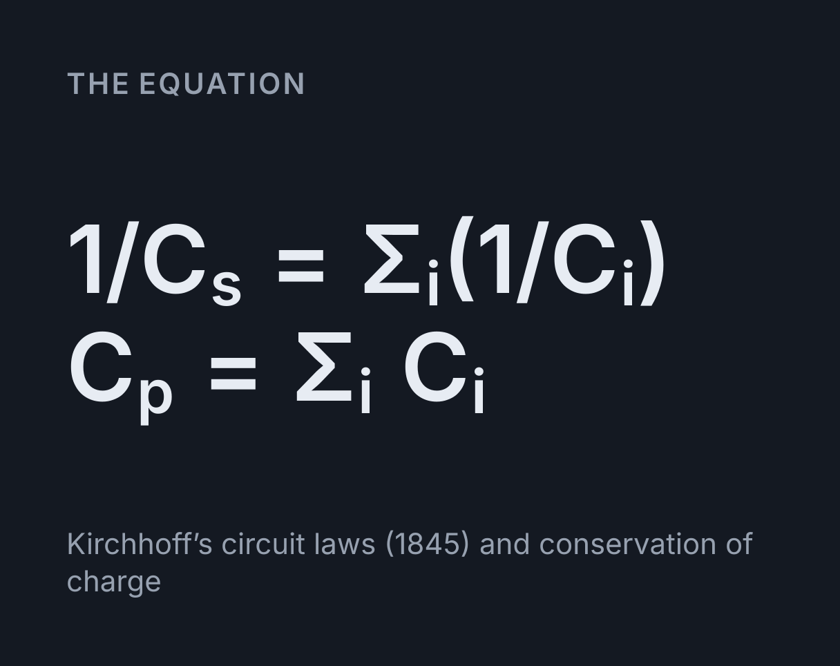
The equation
Kirchhoff’s circuit laws (1845) and conservation of charge
Capacitors in series and parallel: the two rules
Capacitors in parallel add, C = C₁ + C₂ + C₃, and capacitors in series add as
reciprocals, 1/C = 1/C₁ + 1/C₂ + 1/C₃. Those are the rules for resistors the other way
round. Capacitors in parallel have both plates joined to the same two points, so they share one
voltage and their charges add. Capacitors in series carry one and the same charge, because the
plates joined between two neighbours form an isolated conductor that starts with no net charge, and
their voltages add, which is why the reciprocals add.
That makes a series combination smaller than its smallest capacitor and a parallel one larger than
its largest. In series the smallest capacitor takes the largest share of the voltage,
V = Q/C; in parallel the largest capacitor holds the most charge,
Q = CV.
How to use it
Choose how the groups connect. As Stages in series, each group is one link in a chain, and two or more capacitors inside a group are in parallel with each other, the same layout as the resistor network calculator. As Branches in parallel, each group is one branch across the supply, and two or more capacitors inside a group are in series. Type the capacitances in the unit chosen in the menu, and a supply voltage if you want the charges.
The headline is the equivalent capacitance, the single capacitor that would draw the same charge from the supply. Below it the table gives every capacitor’s own voltage, charge and stored energy, and the working shows each step with your numbers. The equivalent capacitance can be carried to the capacitor energy calculator or the RC time constant calculator, which each take one capacitance.
Worked example: 12 µF in series with 2 µF and 4 µF
This is the network loaded above, and it is Example 8.7 in OpenStax
University Physics Volume 2 (Ling, Sanny and Moebs, 2016), section 8.2. The 2 µF and 4 µF are
in parallel, so they add: 2 + 4 = 6 µF. That pair is in series with the 12 µF, so
1/C = 1/12 + 1/6 = 1/4, and C = 4 µF, below the 6 µF of the smaller stage.
On a 12 V supply the charge drawn is Q = 4 µF × 12 V = 48 µC, and both stages carry that
same charge. The 12 µF takes 48 µC / 12 µF = 4 V and the pair takes
48 µC / 6 µF = 8 V, which add back to the 12 V supply. Inside the pair both capacitors
have 8 V, so the 2 µF holds 2 µF × 8 V = 16 µC and the 4 µF holds
4 µF × 8 V = 32 µC, which add back to 48 µC.
The energy stored is ½ × 4 µF × (12 V)² = 288 µJ, shared as 96 µJ in the 12 µF, 64 µJ in
the 2 µF and 128 µJ in the 4 µF. Example 8.8 in the book works the same energies to two figures,
giving 130 µJ for the 4 µF and 0.29 mJ in all. Switch the arrangement to Branches in parallel and the
same three numbers describe the 12 µF across a series pair of 2 µF and 4 µF, and the network becomes
13.333 µF.
Worked example: two in series with a third across them
Example 8.6 in the same section puts 1 µF and 5 µF in series and connects 8 µF across the pair.
Choose Branches in parallel, with 1 and 5 in the first branch and 8 in the second. The series pair
gives 1/C = 1/1 + 1/5 = 1.2, so C = 0.83333 µF, and the branches add:
0.83333 + 8 = 8.8333 µF, which the book rounds to 8.833 µF.
With 12 V applied, the pair holds 0.83333 µF × 12 V = 10 µC, which is the charge on each
of its two capacitors, so the 1 µF takes 10 µC / 1 µF = 10 V and the 5 µF takes
10 µC / 5 µF = 2 V. The 8 µF has the full supply across it and holds
8 µF × 12 V = 96 µC. The supply delivers 106 µC in all, which is
8.8333 µF × 12 V.
Shortcuts worth knowing
Two capacitors in series combine as the product over the sum, C = C₁C₂/(C₁ + C₂), and n
equal capacitors in series give C/n. Two in series across a supply form a capacitive divider: the
voltage on the first is V₁ = V × C₂/(C₁ + C₂), with the other capacitor’s value on top,
the reverse of a resistive divider. A very small capacitor in series with a large one sets the total
almost on its own: 5 pF in series with 1 µF is still just under 5 pF.
What this does not cover
The capacitors are ideal: Q = CV exactly, with no tolerance, leakage or voltage rating.
Real aluminium electrolytics are commonly ±20 percent, so five figures here are arithmetic rather
than accuracy, and because leakage currents differ, a real series stack does not share its voltage
by capacitance alone, which is why high-voltage stacks carry balancing resistors across each part.
Every capacitor is taken to start uncharged, and the results are the steady state after charging
has finished. The charging itself, and how long it takes, is what the
RC charge and discharge simulator shows.
The network has two levels: groups in series with capacitors in parallel inside each, or groups in parallel with capacitors in series inside each. A bridge, or a network nested more deeply, is out of scope; reduce the innermost part first and type its equivalent as one capacitor.
Common mistakes
- Using the resistor rules. Adding 12 µF and 6 µF in series gives 18 µF, when the answer is 4 µF. Series capacitance is always below the smallest capacitor.
- Forgetting the final reciprocal.
1/12 + 1/6is 0.25, which is not the answer. The answer is one over that, 4 µF. - Sharing the voltage equally in series. Capacitors in series share the charge, and the smallest one takes the largest voltage, so it is the one whose rating matters most.
- Adding the charges along a chain. Each stage holds the same charge, and the supply delivers it once: the supply delivers only 48 µC in the example above, not 96 µC.
- Mixing units. A capacitance in microfarads times a voltage in volts is a charge in microcoulombs. The calculator works in farads throughout and adds prefixes only for reading.
Converting units first? Use the capacitance conversion table.
Common questions
How do you add capacitors in series and in parallel?
In parallel you add them, C = C₁ + C₂ + C₃, and in series you add their reciprocals, 1/C = 1/C₁ + 1/C₂ + 1/C₃, which is the reverse of the rules for resistors. Capacitors in parallel share one voltage and their charges add, so the capacitances add. Capacitors in series share one charge and their voltages add, so the reciprocals add. Two 10 µF capacitors make 20 µF in parallel and 5 µF in series.
Do capacitors in series have the same charge?
Yes. Every capacitor in a series chain carries the same charge, because the plates joined by the wire between two neighbours form an isolated conductor with no net charge, so the −Q drawn onto one leaves +Q on the other. It is the voltages that differ, V = Q/C, so the smallest capacitor takes the largest voltage. In the network this calculator opens with, 48 µC passes through both stages, and the 12 µF stage takes 4 V while the 6 µF parallel pair takes 8 V.
How do you find the voltage across each capacitor in series?
Divide the shared charge by each capacitance, V = Q/C, after finding that charge from the equivalent capacitance, Q = C × V. For 2 µF and 3 µF in series across 10 V, the equivalent capacitance is 1.2 µF and the charge is 12 µC, so the 2 µF takes 6 V and the 3 µF takes 4 V, which add back to 10 V. For exactly two capacitors the shortcut is V₁ = V × C₂/(C₁ + C₂), with the other capacitor’s value on top.
Why is the series capacitance smaller than the smallest capacitor?
Because each capacitor in the chain adds its own Q/C to the voltage needed for the same charge, so less charge is stored per volt, and charge per volt is what capacitance is. Two identical parallel-plate capacitors in series act like one with twice the gap between its plates, and in parallel like one with twice the plate area. For example, 1 µF, 5 µF and 8 µF give 0.755 µF in series and 14 µF in parallel. A series answer that is not below the smallest capacitor has a slip in it, usually a missing final reciprocal.
How do I enter three capacitors in series with a fourth across them?
Choose Branches in parallel, then put the three series capacitors in one branch and the fourth in a branch of its own. Branches share the supply voltage and the capacitors inside a branch share a charge, so four 10 µF capacitors arranged that way across 500 V give 13.333 µF in total, with 1.667 mC and 166.7 V on each of the three and 5 mC at the full 500 V on the fourth. A chain, such as one capacitor in series with a parallel pair, uses Stages in series instead.