Free-Body Diagram Maker
Free body diagram maker that draws forces to scale, resolves each into x and y components, and finds the net force, its direction and the acceleration.
Visualiser
Free-body diagram, to scale, of a 10 kg block pulled by a rope at 30° above the horizontal. Forces: weight W, 98.1 N straight down; normal force N, 73.1 N straight up; pull of the rope T, 50 N at 30°, up and to the right; kinetic friction f, 21.93 N to the left. The net force is 21.37 N to the right, so the acceleration is 2.137 m/s². In a second panel the forces are drawn tip to tail, with the net force from the start to the finish.
- Net force Fnet = √((ΣFx)² + (ΣFy)²) = √(21.37² + 0²): the one force that does what all of them do together.
- 21.37 N
- Direction of the net force To the right. Measured anticlockwise from the positive x axis, it is the angle whose tangent is ΣFy / ΣFx, in the quadrant the signs of the two sums give.
- 0°
- Acceleration a = Fnet / m = 21.37 / 10, in the direction of the net force, which is Newton’s second law.
- 2.137 m/s²
- Forces balance ΣFx is not zero, so the forces leave a net force and the object accelerates.
- No
- ΣFx Every force’s x component, F cos θ, added with its sign: to the right is positive.
- 21.37 N
- ΣFy Every force’s y component, F sin θ, added with its sign: upwards is positive.
- 0 N
- Normal force N = m g − T sin φ = 98.1 − 25: the rope takes part of the weight off the floor.
- 73.1 N
- Kinetic friction μk N = 0.3 × 73.1 N, against the slide, whatever the speed.
- 21.93 N
- Most static friction can give μs N = 0.5 × 73.1 N. The block stays put while the force trying to slide it is no more than this.
- 36.55 N
| Force | Size (N) | Angle | x (N) | y (N) |
|---|---|---|---|---|
| W Weight | 98.1 | 270° | 0 | −98.1 |
| N Normal force | 73.1 | 90° | 0 | 73.1 |
| T Pull of the rope | 50 | 30° | 43.3 | 25 |
| f Kinetic friction | 21.93 | 180° | −21.93 | 0 |
| Net force | 21.37 | 0° | 21.37 | 0 |
Working
- T: x = 50 cos 30° = 43.3 N, y = 50 sin 30° = 25 N
- ΣFx = 43.3 − 21.93 = 21.37 N
- ΣFy = −98.1 + 73.1 + 25 = 0 N
- Fnet = √(21.37² + 0²) = 21.37 N, to the right
- a = Fnet / m = 21.37 / 10 = 2.137 m/s²
Citing this tool
Last updated . Add the date you accessed it as well, which a citation of a page that can change asks for. If a specific result matters, cite the permalink from the tool’s share row instead of this page: it reproduces the exact parameters.
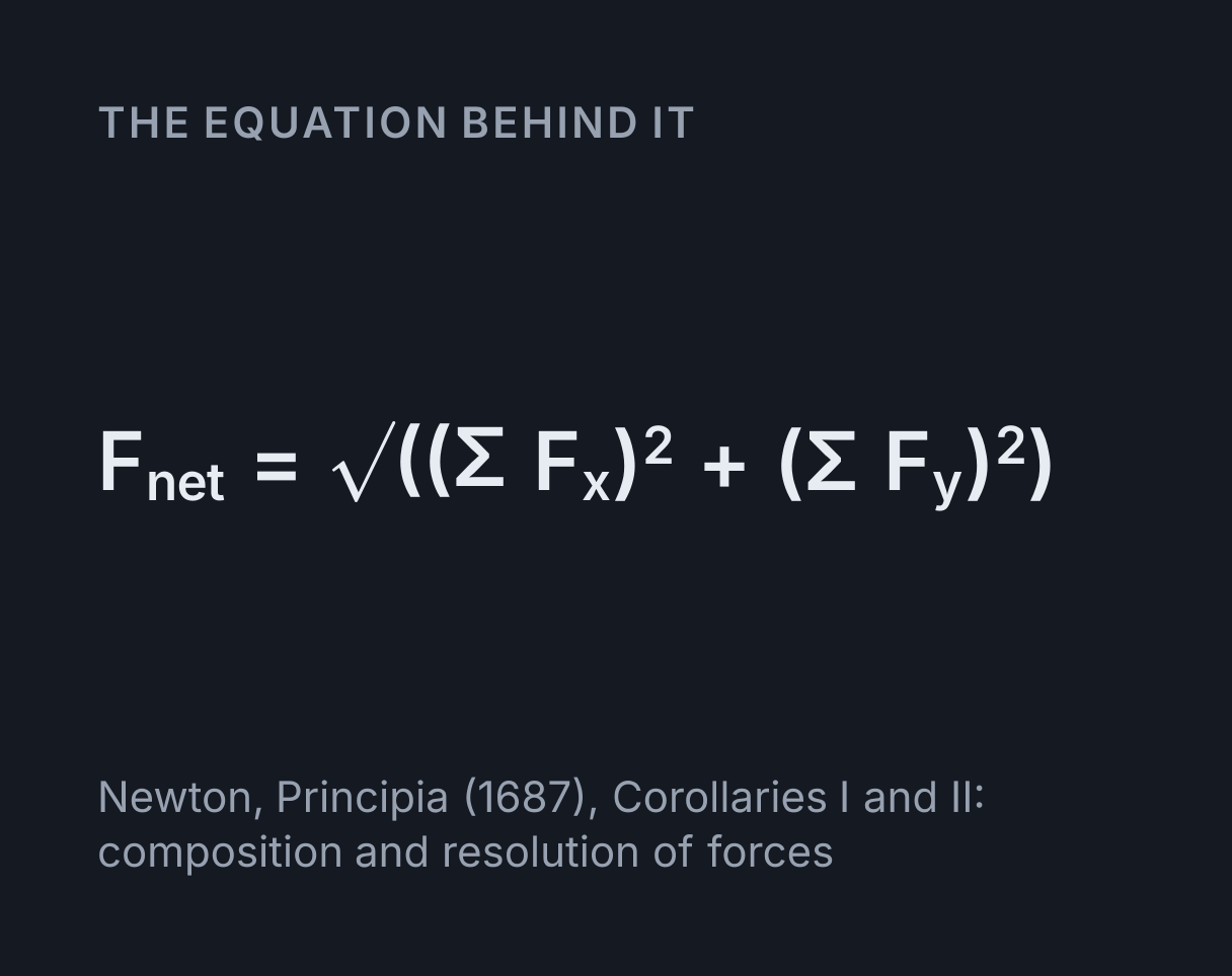
The equation
Newton, Principia (1687), Corollaries I and II: composition and resolution of forces
What is a free-body diagram?
A free-body diagram shows one object on its own, drawn as a dot, with an arrow for every force
acting on it. Each arrow starts at the dot, points the way its force acts and is drawn to scale,
so a force twice as large has an arrow twice as long. Added together, the forces give the net
force. With the components of every force summed along two perpendicular axes, its size is
Fnet = √((ΣFx)² + (ΣFy)²). Divided by the mass, the net force gives the
acceleration, which is Newton’s second law, the same F = ma the
force calculator solves.
This free-body diagram maker draws that diagram for five standard situations and for any set of up to six forces of your own. It resolves every force into components, adds them, draws the net force as a shaded arrow and lays the forces tip to tail in a second panel, so you can see whether they close up. A table under the diagram lists every component with the working, and the readouts give the net force, its direction, the acceleration and whether the forces balance.
Using the free-body diagram maker
Choose a situation first: a block pushed along a floor, a block pulled by a rope at an angle, a block on a slope, a weight hanging from two ropes, or a mass on scales in a lift. Each works out its own forces from the settings under it, which are the mass, the push or the rope’s tension and angle, the slope angle, the two coefficients of friction, the rope angles, the lift’s acceleration and the strength of gravity. Only the settings a situation uses are shown.
To build a diagram of your own, choose Your own forces. Set the number of forces, pick the one to edit, and give it a label of up to eight characters, a size in newtons and a direction in degrees, measured anticlockwise from the positive x axis: 0° points right, 90° up, 180° left and 270° down. The force being edited is drawn in a second colour, with its angle marked and its components dashed.
Every arrow is labelled with its symbol over its size. The dashed arrows along the axes are components, not extra forces, and the faint lines from each tip back to the axes close the rectangle the components make. The shaded arrow is the net force. Turn off the tip-to-tail panel to give the diagram the whole canvas, and use Save image under it to download the diagram as a picture. Copy these readings puts the readouts and every component on the clipboard as text.
Worked example: a 10 kg block pulled at 30°
The maker opens on this case: a 10 kg block on a wooden floor, pulled by a rope with a tension of 50 N at 30° above the horizontal, with μs = 0.5, μk = 0.3 and g = 9.81 m/s².
- Weight, straight down:
W = mg = 10 × 9.81 = 98.1 N. -
The rope, resolved:
Tx = 50 cos 30° = 43.30 Nalong the floor andTy = 50 sin 30° = 25.00 Nupwards. -
The block stays on the floor, so the vertical forces balance and the floor pushes up with
N = 98.1 − 25.00 = 73.1 N, less than the weight because the rope holds some of it. -
Static friction can give at most
μs N = 0.5 × 73.1 = 36.55 N, less than the 43.30 N pulling the block along, so it slides. -
Kinetic friction then acts against the slide:
f = μk N = 0.3 × 73.1 = 21.93 N, to the left. -
Adding the components:
ΣFx = 43.30 − 21.93 = 21.37 NandΣFy = 73.1 + 25.00 − 98.1 = 0 N. -
So the net force is 21.37 N to the right, and
a = Fnet / m = 21.37 / 10 = 2.137 m/s².
Those are the readouts at the opening settings. In the tip-to-tail panel the four forces run up the rope, up the normal force, back along friction and down the weight, and they finish 21.37 N short of where they started. That gap, along the floor, is the net force.
Resolving forces into components
A force F at an angle θ, measured anticlockwise from the positive x axis, has components
Fx = F cos θ and Fy = F sin θ. The signs take care of themselves: a
40 N force at 210°, down and to the left, has Fx = 40 cos 210° = −34.64 N and
Fy = 40 sin 210° = −20.00 N. Pythagoras puts a force back together from its
components, F = √(Fx² + Fy²), which is exactly how the net force is found from the two sums.
The direction needs more care than the size. tan θ = Fy / Fx gives the angle only to within half a turn: for the 40 N force, tan⁻¹(−20.00 / −34.64) is 30°, the direction straight opposite. The angle has to go in the quadrant the signs give, which for two negative components is between 180° and 270°, so 210°. The maker does this with the two-argument arctangent that programming languages call atan2.
Any pair of perpendicular axes gives the same net force, so it pays to choose the pair that leaves the least to resolve. On a level floor that is horizontal and vertical. On a slope it is along the slope and across it, which the Resolve along the slope setting does: the normal force and friction then lie on the axes, and only the weight has two components.
Why pulling at an angle can help
Tilting the rope loses some forward pull, since only T cos φ acts along the floor, but it also
lifts some of the weight off the floor, which cuts the normal force and with it the friction.
For the opening block, a horizontal 50 N pull leaves ΣFx = 50 − 0.3 × 98.1 = 20.57 N
and an acceleration of 2.057 m/s², less than the 21.37 N at 30°.
The best angle is where tan φ = μk, which for μk = 0.3 is 16.7°. Set the rope angle to 16.7° and the net force rises to 22.77 N, an acceleration of 2.277 m/s². Steeper than that, the forward pull lost outweighs the friction saved. Push down on a handle instead, with a negative angle, and the push adds to the normal force, so friction grows and the block is harder to move.
Static friction is only as large as it needs to be
Choose the block pushed along a floor. The opening push of 30 N leaves the block still, met by static friction of exactly 30 N, although static friction could give up to μs N = 0.5 × 98.1 = 49.05 N. μs N is a ceiling, not a value: below it, friction matches whatever tries to slide the block, and the forces balance.
The maker reproduces Example 6.10 in OpenStax University Physics, a 20.0 kg crate with μs = 0.700, μk = 0.600 and g = 9.80 m/s². The floor pushes up with 196 N, so the most static friction can give is 0.700 × 196 = 137.2 N, and pushes of 20, 30 and 120 N leave the crate still. At 180 N it slides, friction drops to 0.600 × 196 = 117.6 N, and it accelerates at (180 − 117.6) / 20.0 = 3.12 m/s². The book prints 3.10 m/s² because it rounds the friction to 118 N first.
A block on a slope
On a slope at θ, the weight resolves into mg sin θ down the slope and mg cos θ into it. The slope
pushes back against the second, so N = mg cos θ, and friction acts along the surface. For the
opening 10 kg block on a 30° slope, 49.05 N pulls it down the slope and
N = 98.1 cos 30° = 84.96 N, so static friction can give at most
0.5 × 84.96 = 42.48 N. That is not enough, so the block slides, kinetic friction is
0.3 × 84.96 = 25.49 N, and the net force is 49.05 − 25.49 = 23.56 N down the slope,
an acceleration of 2.356 m/s².
That is also the acceleration the inclined plane simulator gives for its 2 kg block, because the mass cancels: every force on the block is proportional to it. Below 26.57°, where tan θ = μs = 0.5, the same block is held by static friction instead, and its three forces close into a triangle tip to tail.
Equilibrium: the tension in two ropes
An object is in equilibrium when the forces on it balance: ΣFx = 0 and
ΣFy = 0. For a weight W hanging from two ropes at θ1 and θ2 above the horizontal, the
sideways balance is T1 cos θ1 = T2 cos θ2 and the upward balance is T1 sin θ1 + T2 sin θ2 = W.
Solved together they give T1 = W cos θ2 / sin(θ1 + θ2) and
T2 = W cos θ1 / sin(θ1 + θ2), a form of Lami’s theorem.
For the opening 10 kg weight on ropes at 30° and 45°, T1 = 71.81 N and T2 = 87.95 N. The steeper rope carries more of the weight, and between them the ropes pull with more than the 98.1 N weight, because their sideways parts cancel and do nothing to hold it up. OpenStax University Physics solves the same problem for a 15.0 kg traffic light hung from wires at 30° and 45° with g = 9.80 m/s², and gets 108 N and 132 N, which the maker gives as 107.6 N and 131.8 N. Lower both ropes to 10° and each pulls with 282.5 N, nearly three times the weight, which is why a washing line can never be pulled straight.
Apparent weight in a lift
On scales in a lift, two forces act: the weight, mg, down, and the push of the scales, N, up.
Their difference gives the mass the lift’s acceleration, N − mg = ma, so N = m(g + a)
with a positive upwards. The scales read N, which is why you feel heavier as a lift sets off
upwards and lighter as it sets off downwards. For the opening 10 kg mass accelerating upwards at
1.2 m/s², N = 10 × (9.81 + 1.2) = 110.1 N, which scales marked in kilograms show as
11.22 kg, and the net force is the 12 N difference.
OpenStax University Physics weighs a 75.0 kg passenger with g = 9.80 m/s²: the scales read 825 N while the lift accelerates upwards at 1.20 m/s² and 735 N at any constant speed. Accelerating downwards at 1.20 m/s², they would read 645 N. At an acceleration of −g they read zero, and a lift accelerating downwards faster than that leaves the passenger behind. A steady acceleration shows on a velocity against time graph as a straight line whose gradient is a, which the motion graphs simulator draws.
What this model leaves out
- Where each force acts. Every force is drawn from one point, which is all the net force needs. A force’s turning effect depends on where it acts, and that needs an extended body and a torque, which the torque calculator works out.
- A block that is already moving. The block starts from rest, so friction is static until the block slides and then points against the slide. A block already sliding the other way, or slowing to a stop, would have kinetic friction pointing the other way.
- Air resistance, upthrust and other forces. Each situation has only the forces named in it. Drag, upthrust or a magnetic force can be added as forces of your own, at the size and direction a problem gives.
- Real ropes and surfaces. The ropes have no mass and do not stretch, and the friction coefficients are the same at any speed and for any area of contact, which is the Amontons and Coulomb model.
- Three dimensions. Every force lies in one plane. A force with a part out of the page needs a third component, ΣFz, added in the same way.
Common mistakes
- Drawing forces the object exerts. A free-body diagram has only the forces on the object. The block pushes down on the floor, but that force acts on the floor, so it belongs on the floor’s diagram.
- Adding ma as a force. The net force is the result of the diagram, not one more force on it. Drawing ma as well counts the forces twice.
- Writing N = mg every time. The normal force is whatever the surface needs to push. A rope pulling up at 30° cuts it from 98.1 N to 73.1 N, and on a slope it is mg cos θ.
- Taking tan⁻¹ without the quadrant. tan⁻¹(Fy / Fx) is the same for a force and its opposite. Check the signs of the components, or use atan2.
- Losing the signs. A component pointing left or down is negative, and the sums have to carry those signs, or balanced forces add up to a net force they do not have.
- Treating static friction as μs N. μs N is the most static friction can give. Pushed with 30 N, the 10 kg block gets 30 N of static friction, not 49.05 N.
- Leaving the calculator in radians. cos 30 in radians is 0.154, not 0.866.
Common questions
How do you draw a free-body diagram?
Draw the object as a dot, then add one arrow for each force acting on it, starting at the dot, pointing the way the force acts and longer for a larger force. Label each arrow: W or mg for the weight, N for the normal force, f for friction and T for a tension. Leave out the forces the object exerts on other things, and do not add the net force or ma as another arrow, because the net force is what the diagram adds up to.
How do you find the net force from a free-body diagram?
Resolve every force into components along two perpendicular axes, F cos θ and F sin θ, add each set with its signs, and combine the two sums by Pythagoras: Fnet = √((ΣFx)² + (ΣFy)²). For a 10 kg block pulled along a floor by a 50 N rope at 30° and sliding with μk = 0.3, ΣFx = 43.30 − 21.93 = 21.37 N and ΣFy = 0, so the net force is 21.37 N forwards and the acceleration is 21.37 / 10 = 2.137 m/s².
What does it mean when the forces on a free-body diagram balance?
The object is in equilibrium: the components add to zero along both axes, ΣFx = 0 and ΣFy = 0, so there is no net force and no acceleration. By Newton’s first law the object stays at rest or keeps moving at a constant velocity, so balanced forces do not mean it is still. Drawn tip to tail, balanced forces close into a polygon, a triangle for three forces, such as a 10 kg weight hanging from ropes at 30° and 45° and held by tensions of 71.81 N and 87.95 N.
How do you resolve a force into components?
Measure the force’s angle θ anticlockwise from the positive x axis and take Fx = F cos θ and Fy = F sin θ. A 50 N pull at 30° above the horizontal has 43.30 N along the floor and 25.00 N upwards, and the components rebuild the force by Pythagoras: (50 cos 30°)² + (50 sin 30°)² = 1875 + 625 = 2500, which is 50². On a slope it is easier to tilt the axes along the surface, so the weight becomes mg sin θ down the slope and mg cos θ into it, and the normal force and friction need no resolving.
How do you find the tension in two ropes holding a weight?
Balance the components. Sideways, T1 cos θ1 = T2 cos θ2, and upwards, T1 sin θ1 + T2 sin θ2 = W, where θ1 and θ2 are the ropes’ angles above the horizontal. Solved together, T1 = W cos θ2 / sin(θ1 + θ2) and T2 = W cos θ1 / sin(θ1 + θ2), so the steeper rope carries more. OpenStax University Physics hangs a 15.0 kg traffic light from wires at 30° and 45° and finds tensions of 108 N and 132 N, which this maker reproduces with g = 9.80 m/s².
What does a scale read in an accelerating lift?
In a lift, or elevator, a scale reads the normal force, N = m(g + a), with a positive when the lift accelerates upwards. For the 75.0 kg passenger in the OpenStax University Physics example, with g = 9.80 m/s², the scale reads 825 N while the lift accelerates upwards at 1.20 m/s² and 735 N at constant speed, the figures OpenStax gives, and 645 N while it accelerates downwards at 1.20 m/s². In free fall it reads zero, because the scale no longer has to push for the passenger to fall with it.