Voltage Drop Calculator
Find the voltage drop and percent drop on copper or aluminum wire by AWG or kcmil size, single-phase or three-phase, with the run in feet or meters.
Calculator
Annealed copper at 100 percent IACS, or EC aluminum at 61 percent, as NEC Chapter 9 Table 8 assumes.
Stranded adds 2 percent, the ASTM allowance for the spiral lay of the strands.
75 °C is the temperature NEC Table 8 lists resistance at. 20 °C is the wire tables’ reference, for a cool run.
Two wires, out and back. A 240 V load on a 120/240 V service is two-wire too.
From the supply to the load, measured once. The formula counts the return conductor.
The load current.
120, 208, 240, 277 or 480 V AC, or 12, 24 or 48 V DC. The percent drop is of this voltage.
- Voltage drop 2 × I × R × L: the current flows out on one conductor and back on the other.
- 3.863 V
- Percent drop Above the 3 percent an NEC informational note gives for a branch circuit, with 5 percent for feeder and branch together. The note is a recommendation, not a requirement.
- 3.219 %
- Voltage at the load The supply voltage less the drop.
- 116.1 V
- Resistance per conductor 6.337 Ω/km. Copper at 75 °C, solid.
- 1.932 Ω/1,000 ft
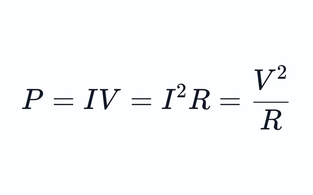
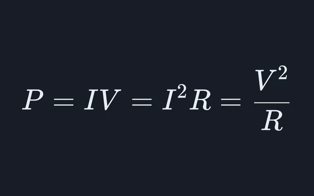
- Power lost in the wire I²R in the two conductors carrying the current, given off as heat.
- 77.3 W
- Longest run for 3 percent One way, at this current, voltage and size.
- 46.6 ft
- Smallest size for 3 percent Of the sizes offered, for this metal, current and run. Voltage drop only: the wire must also have the ampacity for the load and its breaker, which NEC Article 310 and 240.4 set and this does not check.
- 10 AWG
- Conductor area 3.309 mm², 2.053 mm (0.0808 in) across.
- 6.53 kcmil
Working, with your numbers
- rho = 1.7241 uohm-cm x (1 + 0.00393 x (75 - 20)) = 2.0968 uohm-cm
- d = 0.127 mm x 92^((36 - 12)/39) = 2.053 mm
- A = pi/4 x d^2 = 3.309 mm2 = 6530 cmil
- R = rho / A = 2.0968 uohm-cm / 3.309 mm2 = 0.006337 ohm/m = 1.932 ohm per 1,000 ft
- L = 50 ft = 15.24 m
- Vd = 2 x I x R x L
- = 2 x 20 A x 0.006337 ohm/m x 15.24 m
- = 3.863 V
- percent drop = Vd / V x 100
- = 3.863 V / 120 V x 100
- = 3.22 %
Resistance only, as DC wire tables give it. On AC, a large conductor’s reactance adds to the drop.
Citing this tool
Last updated . Add the date you accessed it as well, which a citation of a page that can change asks for. If a specific result matters, cite the permalink from the tool’s share row instead of this page: it reproduces the exact parameters.
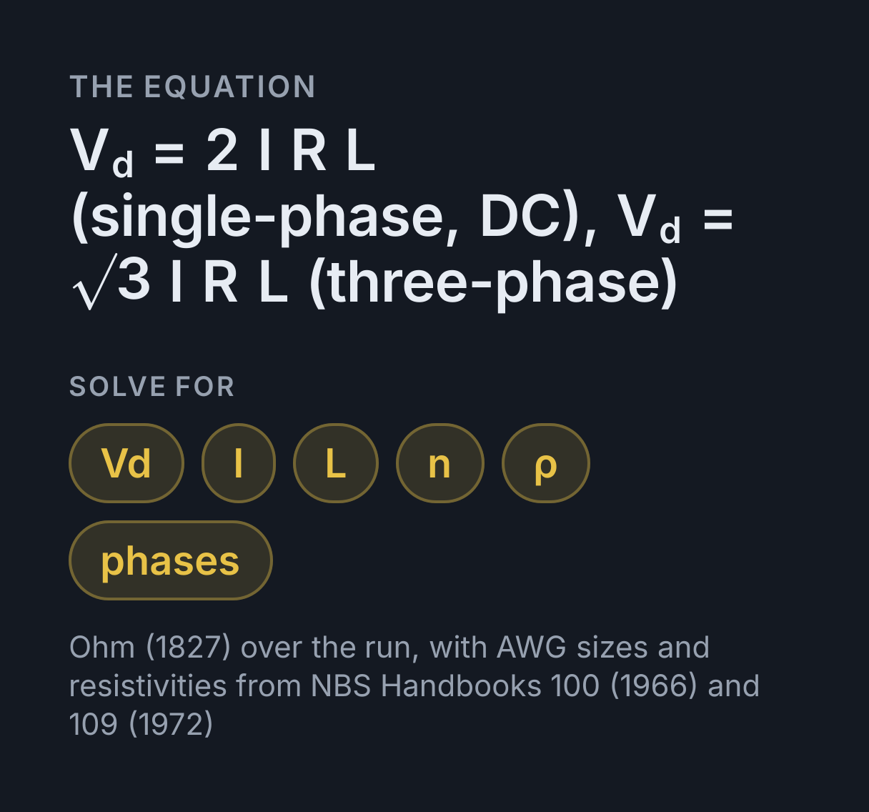
The equation
Ohm (1827) over the run, with AWG sizes and resistivities from NBS Handbooks 100 (1966) and 109 (1972)
How do you calculate voltage drop?
Multiply the current by the resistance of the wire. For a single-phase or DC circuit, Vd = 2 × I × R × L, with I the current in amperes, R the resistance of one conductor per foot or meter, and L the one-way length. Balanced three-phase circuits use √3 instead of 2. Percent drop is Vd ÷ supply voltage × 100.
From wire gauge to ohms per foot
The American Wire Gauge is fixed by two sizes: 0000 is 0.4600 in across and 36 is 0.0050 in,
with 38 sizes between them in a geometric series (NBS Handbook 100, Copper Wire Tables,
1966). Each step changes the diameter by the 39th root of 92, so
d = 0.127 mm × 92^((36 − n)/39), with 1/0 to 4/0 counted as n = 0 to −3. Three steps
multiply the area by 2.005, which is why going three gauge sizes larger halves the
resistance, and with it the drop.
Above 4/0, sizes are named by area in kcmil, thousands of circular mils, up to 2,000 kcmil here. A
circular mil is the area of a circle one mil, 0.001 in, across, so a round wire’s area in
circular mils is its diameter in mils squared: 12 AWG is 80.81 mils across and 6530
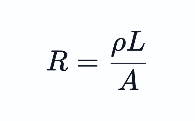
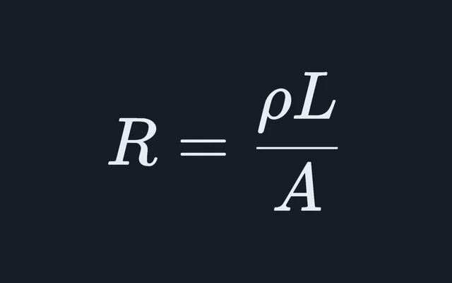
circular mils. One kcmil is 0.5067 mm². The resistance of a conductor per unit length is
its resistivity divided by that area, R = ρ / A, the relation the
wire resistance calculator solves for any
material and length.
Copper and aluminum at 20 °C and 75 °C
Copper wire tables use the International Annealed Copper Standard: 1.7241 µΩ·cm at 20 °C, with resistance rising 0.393 percent per °C (NBS Handbook 100). The aluminum here is the electrical grade at 61 percent of that standard’s conductivity, 2.8264 µΩ·cm at 20 °C and rising 0.403 percent per °C (NBS Handbook 109, Aluminum Wire Tables, 1972). Corrected linearly to 75 °C, the temperature NEC Chapter 9 Table 8 lists conductor resistance at, copper reaches 2.097 µΩ·cm and aluminum 3.453. The table below is worked from those.
| Size | Copper, solid | Copper, stranded | Aluminum, stranded |
|---|---|---|---|
| 14 AWG | 3.07 | 3.13 | 5.16 |
| 12 AWG | 1.93 | 1.97 | 3.24 |
| 10 AWG | 1.21 | 1.24 | 2.04 |
| 8 AWG | 0.764 | 0.779 | 1.28 |
| 6 AWG | 0.48 | 0.49 | 0.807 |
| 4 AWG | 0.302 | 0.308 | 0.508 |
| 2 AWG | 0.19 | 0.194 | 0.319 |
| 1/0 AWG | 0.12 | 0.122 | 0.201 |
| 2/0 AWG | 0.0948 | 0.0967 | 0.159 |
| 4/0 AWG | 0.0596 | 0.0608 | 0.1 |
For solid copper these match NEC Chapter 9 Table 8 to the figures it prints: 3.07, 1.93
and 1.21 Ω per 1,000 ft for 14, 12 and 10 AWG. Stranded wire has slightly more resistance than
a solid rod of the same area, because each strand spirals and is longer than the cable; ASTM allows
2 percent for it, the figure used here. In US units the drop is often written
VD = 2 × K × I × L ÷ CM, with the area CM in circular mils and K the resistivity in
ohm circular mils per foot: 10.37 for copper and 17 for aluminum at 20 °C, 12.61 and
20.77 at 75 °C.
Where the 3 and 5 percent figures come from
They come from an informational note to section 210.19 of the National Electrical Code, NFPA 70, which says that branch-circuit conductors “sized to prevent a voltage drop exceeding 3 percent at the farthest outlet of power, heating, and lighting loads, or combinations of such loads, and where the maximum total voltage drop on both feeders and branch circuits to the farthest outlet does not exceed 5 percent, provide reasonable efficiency of operation.” Section 90.5(C) says informational notes are not enforceable as requirements of the Code, so the 3 percent is a recommendation, not a requirement.
Voltage drop is also not what sizes a wire for safety. Ampacity does that: NEC Article 310 and the overcurrent rules of 240.4 set the smallest conductor a load and its breaker may use, and voltage drop can only call for a larger one. At the full rating of the largest breaker 240.4(D) allows on each, a 120 V run of solid copper at 75 °C reaches 3 percent at 39.1 ft for 14 AWG on 15 A, 46.6 ft for 12 AWG on 20 A and 49.4 ft for 10 AWG on 30 A. On 240 V each distance doubles, because 3 percent of the supply is twice as many volts.
Single-phase, DC and three-phase circuits
In a two-wire circuit, DC or single-phase AC, the current runs the length of the run out and the same length back, so the loop holds twice the wire. A 240 V water heater on a 120/240 V service is two-wire in this sense: its current goes out on one hot conductor and returns on the other.
A balanced three-phase load sends no current back at all, since the three line currents add to zero. Each line drops I × R × L, and because a line-to-line voltage is √3 times a line-to-neutral voltage, the drop between lines is √3 times that. The percent drop is then taken against the line-to-line voltage, such as 208 V or 480 V, with the line current. Using the single-phase 2 instead overstates a three-phase drop by 15.5 percent.
What the formula leaves out
- Reactance. The calculation uses DC resistance, which is the whole answer for DC and close to it for small conductors on AC. In a large conductor on AC, skin effect raises the resistance, and the inductance of the run adds a drop that grows as the power factor falls. NEC Chapter 9 Table 9 gives AC resistance and reactance for that case.
- The real conductor temperature. A copper conductor at 90 °C, the rating of common building wire insulation, has 4.8 percent more resistance than at 75 °C.
- A changing current. The formula takes the current as fixed. A resistive heater draws less current at a lower voltage and a loaded motor draws more, so a large drop changes the current it was worked from. The power the wire wastes is I²R; the electrical power calculator gives the load’s own.
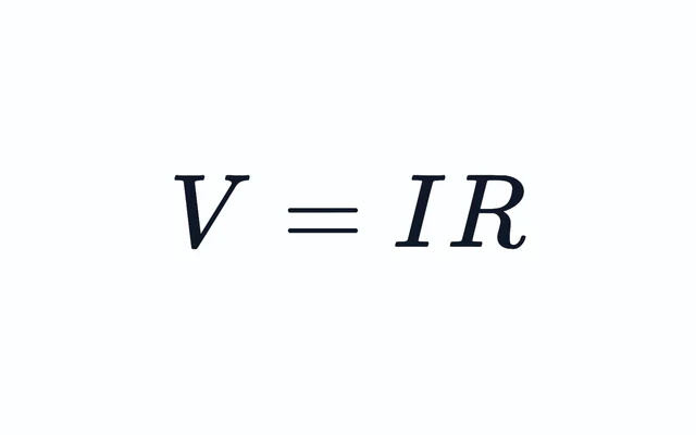
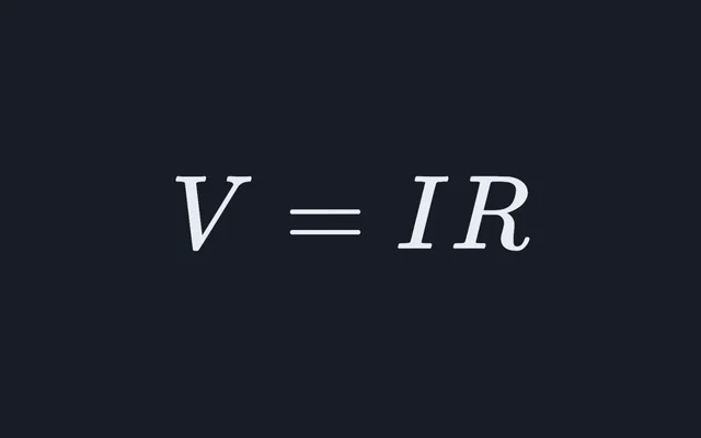
The drop itself is Ohm’s law, V = IR, applied to the wire as a resistance in series with the load. For a two-wire circuit the Ohm’s law calculator gives the same volts from the current and the resistance of both conductors together.
Common mistakes
- Doubling the length and then using the 2. The 2 already counts the return conductor, so a 100 ft run is entered as 100 ft. Entering 200 ft doubles the answer.
- Using 20 °C resistance for a loaded circuit. Copper’s resistance at 75 °C is 21.6 percent higher than at 20 °C, so a drop worked at 20 °C reads low.
- Comparing a three-phase drop with 120 V or 277 V. The √3 formula gives the drop between lines, so it is a percentage of the line-to-line voltage.
- Swapping copper for aluminum at the same gauge. Aluminum at 75 °C has 1.65 times the resistivity of copper. Two gauge sizes larger adds 59 percent to the area, not quite enough to make up for it.
Converting units first? Use the length, electric current, voltage and resistivity conversion tables.
Worked examples
Each one runs through the calculator above, so the arithmetic here is the arithmetic it does.
What is the voltage drop on 100 ft of 12 AWG copper wire at 20 amps?
- d = 0.127 mm x 92^((36 - 12)/39) = 2.053 mm
- A = pi/4 x d^2 = 3.309 mm2 = 6530 cmil
- R = rho / A = 2.0968 uohm-cm / 3.309 mm2 = 0.006337 ohm/m = 1.932 ohm per 1,000 ft
- L = 100 ft = 30.48 m
- Vd = 2 x I x R x L
- = 2 x 20 A x 0.006337 ohm/m x 30.48 m
- = 7.726 V
7.73 V, which is 6.44 percent of a 120 V circuit, more than twice the 3 percent the NEC’s informational note suggests. The length is the 100 ft run, not the 200 ft of wire in the loop: the 2 in the formula already counts the return conductor.
How far can you run 12 gauge wire on a 20 amp circuit for a 3 percent voltage drop?
- d = 0.127 mm x 92^((36 - 12)/39) = 2.053 mm
- A = pi/4 x d^2 = 3.309 mm2 = 6530 cmil
- R = rho / A = 2.0968 uohm-cm / 3.309 mm2 = 0.006337 ohm/m = 1.932 ohm per 1,000 ft
- L = Vd / (2 x I x R)
- = 3.6 V / (2 x 20 A x 0.006337 ohm/m)
- = 46.59 ft = 14.2 m
46.6 ft, one way, since 3 percent of 120 V is 3.6 V. On a 240 V circuit the allowance is 7.2 V and the distance doubles to 93.2 ft, and at half the current, 10 A, the run can also be twice as long.
What is the three-phase voltage drop on 250 ft of 4 AWG copper at 60 amps and 480 V?
- d = 0.127 mm x 92^((36 - 4)/39) = 5.189 mm
- A = pi/4 x d^2 = 21.15 mm2 = 41,740 cmil
- R = rho / A = 2.0968 uohm-cm / 21.15 mm2 = 0.0009914 ohm/m = 0.3022 ohm per 1,000 ft
- L = 250 ft = 76.2 m
- Vd = sqrt(3) x I x R x L
- = 1.732 x 60 A x 0.0009914 ohm/m x 76.2 m
- = 7.851 V
7.85 V between lines, 1.64 percent of 480 V. The single-phase formula would give 9.07 V, 15.5 percent too high, because a balanced three-phase load sends no current back on a return conductor.
Practise this with Electricity Practice Problems, questions generated from this calculator and 11 other calculators in Electricity.
Common questions
Is a 3 percent voltage drop required by the NEC?
No. The 3 percent figure is in an informational note to NEC section 210.19, which says branch circuits sized for no more than 3 percent at the farthest outlet, with no more than 5 percent across feeder and branch circuit together, provide reasonable efficiency of operation. Section 90.5(C) says informational notes are not enforceable as requirements of the Code. The minimum conductor size the NEC does require comes from ampacity and overcurrent protection.
Do I use the one-way or round-trip length for voltage drop?
The one-way length, from the supply to the load. The 2 in the single-phase formula already counts the return conductor, so entering the round trip doubles the drop. For three-phase, √3 takes the place of the 2 and the length is still one way.
How much more voltage drop does aluminum wire have than copper?
About 1.65 times as much for the same gauge at 75 °C, the ratio of their resistivities: aluminum at 61 percent of the annealed copper standard’s conductivity, against 100 percent for copper. Going two gauge sizes larger adds 59 percent to the area, so 4 AWG aluminum still drops slightly more than 6 AWG copper on the same run.
Why does the calculator default to 75 °C?
NEC Chapter 9 Table 8 lists conductor resistance at 75 °C, and a conductor carrying load runs warmer than the 20 °C the wire tables are referenced to. Resistance rises with temperature: copper’s is 21.6 percent higher at 75 °C than at 20 °C, and aluminum’s 22.2 percent. Choose 20 °C for a run that stays near room temperature.
What is the formula for three-phase voltage drop?
Vd = √3 × I × R × L for a balanced load, with I the line current, R the resistance of one conductor per unit length and L the one-way length. The result is the drop between lines, so the percent drop is taken against the line-to-line voltage, such as 208 V or 480 V. Using the single-phase 2 instead overstates the drop by 15.5 percent.