Moment of Inertia and Section Modulus Calculator
Moment of inertia Ix and Iy, section modulus, centroid and radius of gyration of I-beam, T-beam, box, tube, rectangle and circle sections, in mm or inches.
Calculator
bf in AISC tables
d in AISC tables
Typed dimensions convert at 25.4 mm to the inch when the unit changes.
- Second moment of area Ix About the horizontal axis through the centroid, the one a beam loaded from above bends about. That is 7999 cm⁴, as UK section tables print it.
- 79.99 × 10⁶ mm⁴
- Second moment of area Iy About the vertical axis through the centroid, the weak axis an unbraced I-section column usually buckles about. That is 602.7 cm⁴, as UK section tables print it.
- 6.027 × 10⁶ mm⁴
- Area A The cross-sectional area. That is 51.88 cm², as UK section tables print it.
- 5188 mm²
- Centroid ȳ Measured up from the bottom edge. x̄ = 75 mm from the left edge, on the axis of symmetry.
- 150 mm
- Section modulus Sx Ix / c with c = 150 mm, half the depth. The bending stress at the top and bottom faces is σ = M / Sx. That is 533.3 cm³, as UK section tables print it.
- 533.3 × 10³ mm³
- Section modulus Sy Iy / (b / 2), for the outer edges of the flange. That is 80.36 cm³, as UK section tables print it.
- 80,360 mm³
- Radius of gyration rx √(Ix / A).
- 124.2 mm
- Radius of gyration ry √(Iy / A). A column’s slenderness is its effective length over the smaller of the two radii.
- 34.08 mm
Working, with your numbers
- A = 2 × b × tf + (h − 2tf) × tw = 2 × 150 × 10.7 + 278.6 × 7.1 = 5188 mm²
- Ix = [b × h³ − (b − tw) × (h − 2tf)³] / 12 = [150 × 300³ − 142.9 × 278.6³] / 12 = 79.99 × 10⁶ mm⁴
- Iy = [2 × tf × b³ + (h − 2tf) × tw³] / 12 = [2 × 10.7 × 150³ + 278.6 × 7.1³] / 12 = 6.027 × 10⁶ mm⁴
- Sx = Ix / (h / 2) = 79.99 × 10⁶ / 150 = 533.3 × 10³ mm³
- Sy = Iy / (b / 2) = 6.027 × 10⁶ / 75 = 80,360 mm³
- rx = √(Ix / A) = √(79.99 × 10⁶ / 5188) = 124.2 mm
- ry = √(Iy / A) = √(6.027 × 10⁶ / 5188) = 34.08 mm
Root fillets are left out, which puts a rolled section a few percent under its table value: the default 300 × 150 mm section gives 7,999 cm⁴ against 8,356 cm⁴ for an IPE 300.
Citing this tool
Last updated . Add the date you accessed it as well, which a citation of a page that can change asks for. If a specific result matters, cite the permalink from the tool’s share row instead of this page: it reproduces the exact parameters.
The equation
Gere and Goodno, Mechanics of Materials, 9th edition (2018)
What is the area moment of inertia?
Ix = ∫ y² dA: every small area dA of a cross-section times the square of its distance y from the x axis, summed over the section, in mm⁴ or in⁴. UK texts call it the second moment of area. Area far from the axis counts most, so depth adds stiffness fast: a rectangle has Ix = bh³/12.
Using the calculator
Pick one of the six shapes, choose millimetres or inches, and type the dimensions. The section redraws to scale with its centroid and its centroidal x and y axes, and the readouts give the area, the centroid, both second moments, the section moduli and the radii of gyration, with every line of the working underneath, ready to copy. The x axis is horizontal, so Ix is the one a beam loaded from above bends about. In millimetres each result also reads in the cm⁴ and cm³ that UK section tables print, and for an I or a T the flange width b and overall depth h are the bf and d of AISC tables.
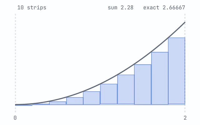
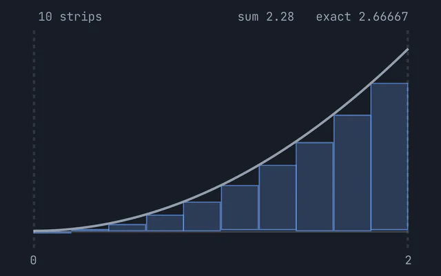
The integral is a sum of thin horizontal strips, each of area dA at height y, which is the same limit the Riemann sum explorer draws for an area under a curve. Every shape here has a closed form for it, from the standard tables in mechanics of materials texts such as Gere and Goodno.
Moment of inertia of an I-beam
An I-section is its bounding rectangle less the two voids beside the web, which is the quickest way to its Ix. The calculator opens on a 300 × 150 mm steel section with 10.7 mm flanges and a 7.1 mm web, the default section of the shear force and bending moment calculator, so the two pages give the same 7,999 cm⁴:
A = 2 × b × tf + (h − 2tf) × tw = 2 × 150 × 10.7 + 278.6 × 7.1 = 5188 mm²Ix = [b × h³ − (b − tw) × (h − 2tf)³] / 12 = [150 × 300³ − 142.9 × 278.6³] / 12 = 79.99 × 10⁶ mm⁴Iy = [2 × tf × b³ + (h − 2tf) × tw³] / 12 = [2 × 10.7 × 150³ + 278.6 × 7.1³] / 12 = 6.027 × 10⁶ mm⁴Sx = Ix / (h / 2) = 79.99 × 10⁶ / 150 = 533.3 × 10³ mm³
The flanges carry the stiffness. The same 5,188 mm² of steel as a solid rectangle 300 mm deep would be 17.29 mm wide, with Ix = 38.91 × 10⁶ mm⁴, so the I-section is 2.06 times as stiff in bending for the same depth and weight. About the vertical axis no steel is more than 75 mm away, against 150 mm about the horizontal one, and Iy is only 7.5 percent of Ix, which is why an unbraced I-section column usually buckles sideways, about its weak axis.
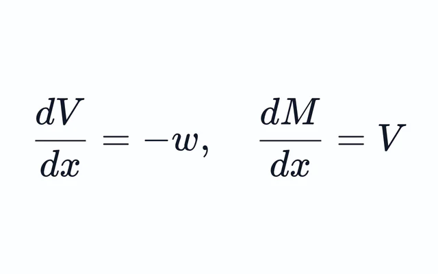
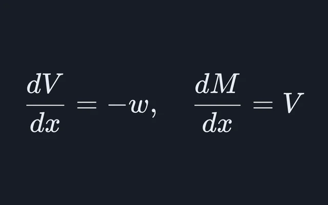
Dividing a bending moment by Sx gives the largest bending stress, σ = M/Sx. The shear
force and bending moment calculator’s default beam peaks at 40 kN·m over its
roller, so the stress there is 40 × 10⁶ N·mm ÷ (533.3 × 10³ mm³) = 75.0 MPa,
the figure that page gives.
Centroid of a T-section and the parallel axis theorem
A T is symmetric only about its vertical axis, so its centroid has to be found first. Split it into a flange and a web, take ȳ = ΣAy / ΣA from the bottom edge, then carry each part’s own second moment to the centroid with the parallel axis theorem, I = Σ(Ī + Ad²), where d is the distance from the part’s centroid to ȳ. Choose T-section and enter a 100 × 20 mm flange on a 20 mm web, 120 mm deep overall:
Flange: Af = b × tf = 100 × 20 = 2000 mm², at yf = h − tf / 2 = 110 mmWeb: Aw = tw × (h − tf) = 20 × 100 = 2000 mm², at yw = (h − tf) / 2 = 50 mmA = Af + Aw = 2000 + 2000 = 4000 mm²ȳ = (Af × yf + Aw × yw) / A = (2000 × 110 + 2000 × 50) / 4000 = 80 mm from the bottomIx = b × tf³ / 12 + Af × (yf − ȳ)² + tw × (h − tf)³ / 12 + Aw × (ȳ − yw)²Ix = 66,670 + 2000 × 30² + 1.667 × 10⁶ + 2000 × 30² = 5.333 × 10⁶ mm⁴
Leaving out the Ad² terms is the classic mistake: the two parts’ own second moments add up to only 1.733 × 10⁶ mm⁴, 33 percent of the answer. Because the centroid sits 40 mm below the top and 80 mm above the bottom, the T has two section moduli about x, 133.3 × 10³ mm³ for the top of the flange and 66,670 mm³ for the foot of the web. The smaller one belongs to the farther face and gives the larger stress, so in a sagging T-beam the foot of the web, in tension, is the critical fibre.
Hollow tubes and box sections
Second moments of area subtract, because each is an integral over the area. A tube is a solid circle less its bore, I = π(D⁴ − d⁴)/64, and a box section is its outer rectangle less its void. Taking out the middle costs little stiffness, since that material sits closest to the axis. In inches, a tube 5 in across with a 0.25 in wall has A = 3.731 in² and I = 10.55 in⁴. A solid round bar with the same area is 2.179 in across and has I = 1.108 in⁴, so the tube is 9.53 times as stiff in bending for the same weight of metal.
That ratio is (D² + d²)/(D² − d²), and it keeps growing as the wall gets thinner. What stops it in practice is local buckling: a very thin wall crumples before the section as a whole is fully stressed, which this calculator does not check.
Section modulus and radius of gyration
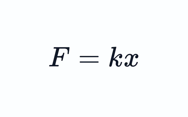
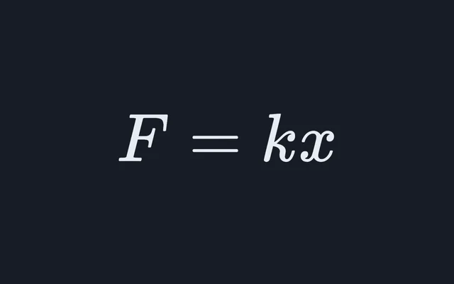
The flexure formula gives the bending stress at a distance c from the neutral axis as σ = Mc/I, so the elastic section modulus S = I/c turns it into σ = M/S, one number that sizes a beam for strength, while I sizes it for stiffness through EI. The radius of gyration r = √(I/A) is the distance from the axis at which the whole area, concentrated, would give the same I. Columns use it: the Euler buckling stress is π²E/(KL/r)², so a column buckles about the axis with the smaller r. EI plays the part for a beam that the spring constant plays in the Hooke’s law calculator: double it and every deflection halves.
The letters swap between countries. In US texts and AISC tables, S is the elastic section modulus and Z the plastic one. UK tables to BS 5950 used Z for the elastic modulus and S for the plastic, and Eurocode 3 writes them Wel and Wpl. Eurocode also names the strong axis y-y and the weak axis z-z, so the Iy in a UK Eurocode section table is the Ix here. This calculator gives the elastic modulus only.
Converting mm⁴, cm⁴ and in⁴
A second moment of area is a length to the fourth power, so its units convert by the fourth power too. One inch is exactly 25.4 mm, so 1 in⁴ = 25.4⁴ mm⁴ = 416,231 mm⁴, or 41.62 cm⁴, and a section modulus goes by the cube, 1 in³ = 16,387 mm³. Going from mm⁴ to cm⁴ divides by 10⁴, not by 10: the default I-section’s 79.99 × 10⁶ mm⁴ is 7,999 cm⁴.
The calculator never converts partway through. Every formula is homogeneous in length, so millimetres in give mm², mm³ and mm⁴ out, and inches give in², in³ and in⁴. Switching the unit converts the dimensions you typed at 25.4 mm to the inch, and an untouched default switches to round numbers in the other unit instead.
Area moment of inertia versus mass moment of inertia
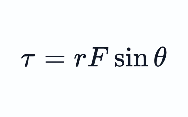
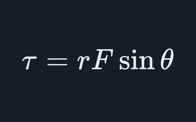
The name is shared with a different quantity. The mass moment of inertia, Σmr², in kg·m² or lb·ft², measures how hard a body is to spin up and appears in τ = Iα. The area moment of inertia has no mass in it: it is a property of a cross-section’s shape, in mm⁴ or in⁴, and it appears in beam bending, σ = My/I, and in beam deflection, EI d²v/dx² = M. Calling it the second moment of area, as UK texts do, keeps the two apart.
What this calculator leaves out
- Fillets and corner radii. A rolled I-section has curved root fillets where the web meets the flanges, and a hollow section has rounded corners. Both are left out, so a catalogue section differs a little: the default I-section gives 7,999 cm⁴ against the 8,356 cm⁴ a section table gives an IPE 300, fillets included.
- Unsymmetric sections. Every shape here is symmetric about its vertical axis, so the product of inertia is zero and x and y are the principal axes. An angle or a Z-section is not, and needs its principal axes found first.
- Plastic modulus and torsion. Only the elastic modulus is given. The polar moment J = Ix + Iy is shown only for the circle and the tube, where it is also the torsion constant. Any other section warps when it is twisted, and its torsion constant is smaller than its polar moment.
- Design checks. Nothing here classifies a section, checks the local buckling of a thin flange or wall, or applies AISC 360 or Eurocode 3. The figures are geometric properties, for coursework and for checking hand calculations.
Common questions
What is the moment of inertia of an I-beam?
For a symmetric I-section, Ix = [bh³ − (b − tw)(h − 2tf)³]/12: the bounding rectangle less the two voids beside the web, where b is the flange width, h the overall depth, tf the flange thickness and tw the web thickness. A section 300 mm deep and 150 mm wide with 10.7 mm flanges and a 7.1 mm web gives 79.99 × 10⁶ mm⁴, or 7,999 cm⁴. Root fillets are left out, so a rolled IPE 300 with those dimensions is listed a few percent higher, at 8,356 cm⁴.
How do you find the centroid of a T-section?
Split it into the flange and the web, multiply each area by the height of its own centroid above the bottom edge, add the products and divide by the total area: ȳ = ΣAy / ΣA. A 100 × 20 mm flange on a 20 × 100 mm web has 2,000 mm² at 110 mm and 2,000 mm² at 50 mm, so ȳ = 80 mm. The parallel axis theorem, I = Σ(Ī + Ad²), then gives Ix = 5.333 × 10⁶ mm⁴.
What is the difference between moment of inertia and section modulus?
The second moment of area I, in mm⁴ or in⁴, sets how stiff a beam is, since its deflection depends on EI. The elastic section modulus S = I/c, in mm³ or in³, where c is the distance from the neutral axis to the farthest fibre, sets the bending stress, σ = M/S. A rectangle 150 mm wide and 300 mm deep has I = bh³/12 = 337.5 × 10⁶ mm⁴ and S = bh²/6 = 2.25 × 10⁶ mm³.
Why does a T-section have two section moduli?
Because its centroid is not at mid-depth, so the top and bottom faces sit at different distances from the neutral axis and S = I/c has a different c for each. A 100 × 20 mm flange on a 20 × 100 mm web has its centroid 40 mm below the top and 80 mm above the bottom, giving 133.3 × 10³ mm³ for the top face and 66,670 mm³ for the bottom. The smaller modulus belongs to the farther face and gives the larger stress.
How do you convert in⁴ to mm⁴ or cm⁴?
Multiply by 25.4 to the fourth power, since one inch is exactly 25.4 mm and a second moment of area is a length to the fourth: 1 in⁴ = 416,231 mm⁴ = 41.62 cm⁴. A section modulus converts by the cube, 1 in³ = 16,387 mm³ = 16.39 cm³. From mm⁴ to cm⁴, divide by 10⁴, not by 10.
Is the area moment of inertia the same as the mass moment of inertia?
No. The mass moment of inertia, in kg·m² or lb·ft², measures how hard a body is to spin up and appears in τ = Iα. The area moment of inertia, in mm⁴ or in⁴, depends only on the shape of a cross-section and appears in beam bending, σ = My/I. UK texts call it the second moment of area, which keeps the two apart.