Shear Force and Bending Moment Diagram Calculator
Drag loads onto a beam and its reactions, shear force and bending moment diagrams (SFD and BMD) and deflection redraw, for cantilevers and overhangs.
Calculator
Drag a load, its round handle, a support or the cut. N selects the next item, the arrow keys move or resize it, and Delete removes a load. Space plays and pauses.
- Reaction at A, the pin Upward positive; a negative reaction pulls the beam down. From ΣFy = 0 once moments about the pin have given the roller: R_A = total load − R_B.
- 23.33 kN
- Reaction at B, the roller Upward positive. From ΣM = 0 about the pin: R_B × 6 m equals the loads’ moments about the pin.
- 56.67 kN
- Largest sagging moment Sagging is positive: the beam curves up at the ends, with tension on the bottom face. The largest is where V crosses zero, or at a load or support.
- 27.22 kN·m, at 2.333 m
- Largest hogging moment Hogging is negative: tension on the top face, as over the support of an overhang or at a cantilever’s wall.
- −40 kN·m, at 6 m
- Largest shear force V is the sum of the upward forces to the left of a section. Where V jumps, the larger side is given.
- −36.67 kN, at 6 m
- Points of contraflexure Where M changes sign, so the beam’s curvature reverses between sagging and hogging.
- 4.667 m
- Largest deflection From EIv″ = M, integrated exactly with the supports’ conditions, for EI = 16,798 kN·m². Small deflections and no shear deformation are assumed.
- 4.804 mm down, at 2.616 m
- Span over deflection For the span, L = 6 m. L/360 is a common reference for floor members under live load (IBC 2021 Table 1604.3), shown for orientation only: this is not a code check.
- L/1,249 within L/360
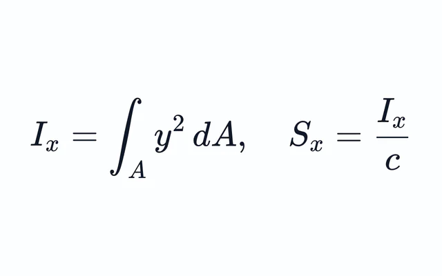
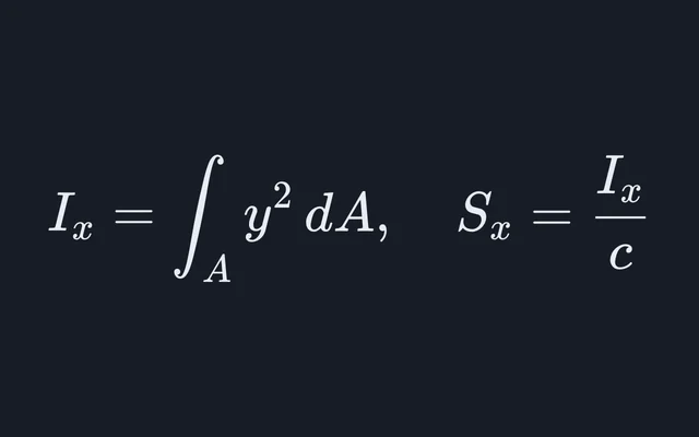
- Peak bending stress σ = Mc/I at the extreme fibre, c = h/2, for the largest moment in size. For reference only: no code check, no safety factor.
- 75.01 MPa, at 6 m
- Flexural rigidity EI E × I = 210 GPa × 7999 cm⁴.
- 16,798 kN·m²
A teaching tool, not a design check: no load factors, no code checks, and L/360 is a common reference, not a test of compliance.
Start from
Loads 2 of 8
- 1. Distributed load 0 m to 6 m 10 kN/m down
- 2. Point load at 8 m 20 kN down
Citing this tool
Last updated . Add the date you accessed it as well, which a citation of a page that can change asks for. If a specific result matters, cite the permalink from the tool’s share row instead of this page: it reproduces the exact parameters.
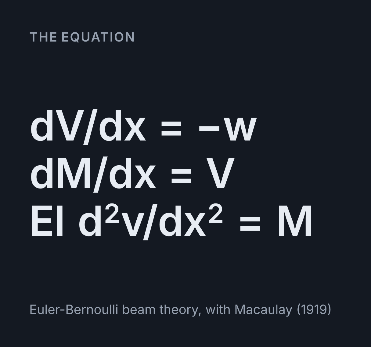
The equation
Euler-Bernoulli beam theory, with Macaulay (1919)
What are the shear force and bending moment differential relationships?
In structural beam mechanics, the internal shear force V(x) and bending moment M(x) follow calculus differential relationships with distributed load w(x): dV / dx = −w(x) and dM / dx = V(x). So the bending moment peaks where the shear force crosses or jumps through zero, and it can also peak at an applied couple or at a cantilever’s fixed end.
Find the reactions first, then cut the beam. At any section, the shear force V is the sum of the upward forces to the left of the cut, and the bending moment M is the sum of their moments about the cut, sagging positive. That is the method of sections, and the calculator does it at every point along the beam at once. It opens on an 8 m beam on a pin at 0 m and a roller at 6 m, so its last 2 m overhang, with a uniform load of 10 kN/m over the span and a 20 kN point load at the free end.
- The reactions. Take moments about the pin, A, where the roller’s reaction has a
lever arm of 6 m:
6 × RB = 10 × 6 × 3 + 20 × 8 = 340, soRB = 56.67 kN. The vertical forces then giveRA = 10 × 6 + 20 − 56.67 = 23.33 kN. - The shear force. Cut between the supports, x metres from A, and add the upward
forces to the left:
V = 23.33 − 10x. It falls at 10 kN/m and is zero atx = 23.33 ÷ 10 = 2.333 m. Just left of the roller it is23.33 − 60 = −36.67 kN. The roller pushes up by 56.67 kN, so just right of it V is +20 kN, and it stays at 20 kN to the tip, where the point load takes it back to zero. - The bending moment. Take moments about the cut of the same forces:
M = 23.33x − 5x². At 2.333 m that is 27.22 kN·m, sagging. Over the roller it is23.33 × 6 − 5 × 36 = −40 kN·m, hogging. On the overhang, M is quickest from the right:M = −20 × (8 − x), which is −40 kN·m at the roller and zero at the tip.
Drag the section cut through the diagrams and the piece to its left lifts off the supports as a free body, carrying its own loads and reactions, with V and M drawn on its face. It balances whatever the cut’s position, which is the method of sections in one picture. Equilibrium is the same idea the free body diagram maker draws for a single body, and taking moments is the arithmetic of the torque calculator.
Using the calculator
Drag a load along the beam, or drag the round handle at the end of its arrow to change its size; take it below the beam and it acts upward. Drag a distributed load’s body to move it, its top line to scale it, or a top corner sideways to stretch it or up and down to make it a triangle or a trapezoid. Turn a couple by dragging round its curved arrow. Drag the pin and the roller to make an overhang at either end, or choose a cantilever and click its wall to move it to the other end. The table under the beam lists every load for exact entry, and the cut reads V, M, the slope θ and the deflection v wherever it is left, snapping to the points that matter as it passes them.
From the keyboard, N steps through the loads, the supports and the cut, the arrow keys move or resize whichever is selected, Delete removes a load and Space starts or stops the sweeping cut. Download data saves V, M, θ and v at 401 points and on both sides of every jump as CSV, and Save image saves all four bands.
The two rules that draw the diagrams for you
Cutting the beam at every point would be slow by hand. Two rules make it quick:
- The slope of the shear force diagram is minus the load intensity:
dV/dx = −w. Under the 10 kN/m load V falls by 10 kN in every metre, which is why the line from 23.33 kN to −36.67 kN is straight. With no distributed load V is flat, and a point load P makes it jump by −P, so a reaction makes it jump up. - The slope of the bending moment diagram is the shear force:
dM/dx = V. Where V is positive M climbs, where V is zero M is flat at a peak or a trough, and where V jumps M only bends. A clockwise couple M₀ makes M jump by +M₀; try the Applied couple preset under Start from.
Together they say that the change in the bending moment between two points is the area under the
shear force diagram between them, plus the jump at any couple in between. From the pin to 2.333 m
the shear force diagram is a triangle of area ½ × 2.3333 × 23.333 = 27.22 kN·m, which is
the moment there. From 2.333 m to the roller
the triangle below the axis has area ½ × 3.6667 × −36.667 = −67.22 kN·m, which takes M
to 27.22 − 67.22 = −40 kN·m, and the overhang’s rectangle of 20 kN × 2 m brings it back to
zero at the tip. Adding up areas is integration, as the
Riemann sum explorer shows, and reading a slope is
differentiation, the other half of the same idea in the
derivative and tangent line explorer.
Where the bending moment is largest
Since dM/dx = V, the bending moment has its peaks and troughs where the shear force
crosses zero, or at a point load or support where V jumps through zero. The default beam has one of
each. V crosses zero at 2.333 m, where the sagging moment peaks at 27.22 kN·m, and V jumps from
−36.67 kN to +20 kN over the roller, where the hogging moment is −40 kN·m. The dashed lines on the
stage join each zero of V to its moment. A peak can also sit where V does neither: at a couple, where
M itself jumps, as on the Applied couple preset, or at a cantilever’s fixed end.
The largest moment in size is the hogging one over the roller, 40 kN·m against 27.22 kN·m, so that
is where the beam is most highly stressed. In the default steel section, 300 mm deep with I =
7,999 cm⁴, worked step by step in the
section properties calculator, the bending stress there is σ = Mc/I = 40 kN·m × 150 mm ÷ 7,999 cm⁴ = 75.0 MPa
at the top and bottom faces, tension on top.
Points of contraflexure
A point of contraflexure is where the bending moment changes sign, so the beam’s curvature turns from
sagging to hogging. On the default beam it is where 23.333x − 5x² = 0, at
x = 23.333 ÷ 5 = 4.667 m, shown as a hollow ring on the moment band. In reinforced concrete
it matters because the tension face changes there, so the main steel has to move from the bottom of
the beam to the top around it. A couple can also take M through zero in a single jump, and the
calculator counts that as a point of contraflexure too.
Deflection by Macaulay’s method
The deflection comes from integrating the moment twice, EI d²v/dx² = M, where E is
Young’s modulus and I the second moment of area. Macaulay’s method, published in 1919, writes M for
the whole beam in one line, with brackets ⟨x − a⟩ that count as zero until x passes a. For the
default beam,
M = 23.33x − 5x² + 5⟨x − 6⟩² + 56.67⟨x − 6⟩, where the third term ends the uniform load at
the roller by adding an equal upward load from there on. Integrating twice,
EIv = 3.889x³ − 0.4167x⁴ + 0.4167⟨x − 6⟩⁴ + 9.444⟨x − 6⟩³ + C₁x + C₂
and the supports fix the constants: v = 0 at the pin gives C₂ = 0, and v = 0 at the roller gives
C₁ = −50 kN·m². With the default steel section, EI = 210 GPa × 7,999 cm⁴ = 16,798 kN·m²,
the span sags at most 4.80 mm, at 2.62 m, and at the tip, where EIv = −33.33 kN·m³, the beam is
1.98 mm down. The calculator does exactly this for any loads, in closed form, which is how it can
give a deflection for cases with no textbook formula.
The largest deflection is not at the largest moment. The sag peaks at 2.62 m while M peaks at 2.33 m, because the deflection at any point depends on the bending along the whole span, and the hogging over the roller lifts the right-hand part of it. The standard cases are each a preset, and each agrees with its formula to every figure shown, for the same steel section:
-
A central point load on a simple span,
δ = PL³/48EI: 20 kN on 6 m deflects 5.36 mm. -
A uniform load on a simple span,
δ = 5wL⁴/384EI: 10 kN/m on 6 m peaks atwL²/8 = 45 kN·mand deflects 10.05 mm, about twice the overhanging beam’s 4.80 mm, because there the tip load’s hogging moment holds the span up. -
A cantilever with an end load,
δ = PL³/3EI: 10 kN on 3 m deflects 5.36 mm, the same as the central load, since10 × 3³ ÷ 3 = 20 × 6³ ÷ 48 = 90. - A cantilever with a uniform load,
δ = wL⁴/8EI: 10 kN/m on 3 m deflects 6.03 mm.
EI is a beam’s stiffness in bending, as k is a spring’s in the Hooke’s law calculator: double it and every deflection halves. The span-to-deflection readout divides the span by its largest deflection: 6 m over 4.80 mm is L/1,249, well inside the L/360 limit, 16.67 mm here, that IBC 2021 Table 1604.3 sets for floor members under live load. For an overhang or a cantilever, L is taken as twice its length, as that table takes it. The comparison is for orientation only and is not a code check.
Which way up: sign conventions
The shear force and bending moment are signed as in Hibbeler’s and Gere’s textbooks. The shear force is
the sum of the upward forces to the left of a section, and the bending moment the sum of their moments
about it, positive when the beam sags, with tension on the bottom face. Loads here are positive downward
and couples positive clockwise, so a downward load makes V fall, dV/dx = −w, and a clockwise
couple makes M jump up. Hibbeler takes a distributed load as positive upward instead, and writes the same
rule as dV/dx = w. The deflection v is positive upward, so a sagging span has a negative v.
Other books and other countries differ. Some sum the forces on the right-hand piece, which turns the shear diagram over. Much UK structural practice draws the bending moment on the tension side of the beam, so a sagging moment appears below the axis. The Moments on the tension side switch draws it that way; only the drawing turns over, and every value stays the same.
Why some beams are not here
Equilibrium gives a beam loaded across its length two equations, ΣFy = 0 and ΣM = 0, which is enough for two unknown reactions: a pin and a roller, or one fixed end. A propped cantilever has three, a beam fixed at both ends has four, and a beam continuous over three supports has three. Those beams are statically indeterminate. Their extra reactions come from compatibility, the condition that the beam bends without leaving its supports, which needs EI as well as the loads. The calculator leaves them out on purpose, so that every number it gives can be checked by hand from two equations, and the buttons under the supports explain why rather than solving a different beam.
What this calculator leaves out
- Design checks. There are no load factors, no load combinations and no code checks, Eurocode, AISC or IS 800. The bending stress and the L/360 comparison are for reference only.
- Shear deformation. It uses Euler-Bernoulli theory: plane sections stay plane, the deflections are small and only bending bends the beam. A short, deep beam also deflects in shear, so it deflects more than this.
- Lateral-torsional buckling. A long, slender beam can twist sideways under a load well short of the one that would overstress it in bending, which this calculator does not consider.
- Self-weight, unless you add it. Add it as a uniform load: the default steel section weighs about 0.40 kN/m at 7,850 kg/m³.
- A varying section. EI is the same along the whole beam, and the I-section’s root fillets are ignored, which puts it at 7,999 cm⁴ against the 8,356 cm⁴ a section table gives an IPE 300. Type I in directly to use a table value.
Common questions
How do you draw a shear force and bending moment diagram?
First find the support reactions from equilibrium. Then walk along the beam: the shear force at any section is the sum of the upward forces to its left, and the bending moment is the sum of their moments about the section. For the default overhanging beam, moments about the pin give 6 × R_B = 10 × 6 × 3 + 20 × 8, so R_B = 56.67 kN and R_A = 23.33 kN.
Where is the bending moment maximum?
Where the shear force crosses zero, or at a point load or support where the shear jumps through zero. On the default beam the shear is zero 2.333 m from the left support, where the sagging moment peaks at 27.22 kN·m. But the largest moment in size is the hogging −40 kN·m over the roller, where the shear jumps from −36.67 to +20 kN. A peak can also sit where the shear does neither: at a couple, where the moment itself jumps, or at a cantilever’s fixed end.
What is a point of contraflexure?
A point where the bending moment changes sign, so the beam changes from sagging to hogging and its curvature reverses. The default beam has one at 4.667 m. In reinforced concrete the main tension steel has to move from the bottom face to the top face around it, because that is where the tension face changes.
Why is the area under the shear force diagram equal to the change in bending moment?
Because dM/dx = V. The moment changes at a rate equal to the shear, so the change in moment between two points is the area under the shear force diagram between them, plus the jump at any couple in between. From the left support to 2.333 m, the shear force diagram is a triangle of area ½ × 2.3333 × 23.333 = 27.22 kN·m, which is the moment there.
How do you calculate the deflection of a cantilever?
For a point load P at the free end, δ = PL³/3EI. For a uniform load w over the whole length, δ = wL⁴/8EI. A 3 m steel cantilever with EI = 16,798 kN·m², the default section here, deflects 5.36 mm under a 10 kN end load and 6.03 mm under 10 kN/m. This calculator integrates EIv″ = M exactly for any mix of loads (Macaulay’s method), so it also covers cases with no textbook formula.
Why can’t I add a third support or fix both ends?
Because the beam would then be statically indeterminate. Equilibrium gives a beam two equations, enough for two unknown reactions, and a third support adds a third. Solving it needs the beam’s bending as well as equilibrium, which this calculator leaves out on purpose so that every number can be checked by hand.
Should the bending moment diagram be drawn above or below the beam?
Both conventions are in use. Mechanics textbooks plot sagging moments as positive, above the axis. Much UK structural practice draws the moment on the tension side of the beam, so sagging appears below it. The values are the same either way: the Moments on the tension side switch changes only the drawing.