Voltage drop chart: how far each wire gauge can run at 120 V and 240 V, copper vs aluminum
At 20 A on 120 V, stranded copper at 75 °C keeps the drop within 3% for 45 ft of 12 AWG, 72 ft of 10 AWG and 115 ft of 8 AWG, one way. On 240 V each run doubles. Aluminum of the same gauge runs 61% as far.
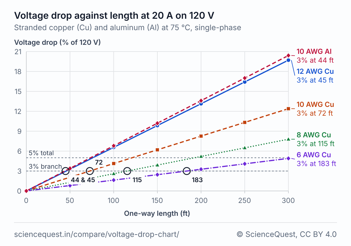
How far each copper gauge can run for a 3% drop
| Size (AWG) | 120 V | 240 V | ||||||
|---|---|---|---|---|---|---|---|---|
| 10 A | 15 A | 20 A | 30 A | 40 A | 50 A | 20 A | 40 A | |
| 14 | 57 | 38 | 28† | 19† | 14† | 11† | 57† | 28† |
| 12 | 91 | 60 | 45 | 30† | 22† | 18† | 91 | 45† |
| 10 | 145 | 96 | 72 | 48 | 36† | 29† | 145 | 72† |
| 8 | 230 | 153 | 115 | 76 | 57 | 46 | 230 | 115 |
| 6 | 367 | 244 | 183 | 122 | 91 | 73 | 367 | 183 |
| 4 | 584 | 389 | 292 | 194 | 146 | 116 | 584 | 292 |
| 3 | 736 | 490 | 368 | 245 | 184 | 147 | 736 | 368 |
| 2 | 928 | 619 | 464 | 309 | 232 | 185 | 928 | 464 |
| 1 | 1,170 | 780 | 585 | 390 | 292 | 234 | 1,170 | 585 |
| 1/0 | 1,476 | 984 | 738 | 492 | 369 | 295 | 1,476 | 738 |
| 2/0 | 1,861 | 1,241 | 930 | 620 | 465 | 372 | 1,861 | 930 |
On 240 V the 3% is 7.2 V against 3.6 V, so every run doubles, and a 240 V run at 20 A equals a 120 V run at 10 A. † The current is more than the overcurrent protection NEC 240.4(D) allows on that size: 15 A for 14 AWG, 20 A for 12 AWG and 30 A for 10 AWG copper [5].
Copper against aluminum at 20 A and 120 V
| Size | Same size | Aluminum to match the copper | ||
|---|---|---|---|---|
| Copper ft | Aluminum ft | Aluminum size | Aluminum run ft | |
| 12 AWG | 45 | 27 | 8 AWG | 70 |
| 10 AWG | 72 | 44 | 6 AWG | 111 |
| 8 AWG | 115 | 70 | 4 AWG | 177 |
| 6 AWG | 183 | 111 | 3 AWG | 223 |
| 4 AWG | 292 | 177 | 1 AWG | 355 |
| 3 AWG | 368 | 223 | 1/0 AWG | 448 |
| 2 AWG | 464 | 281 | 2/0 AWG | 565 |
| 1 AWG | 585 | 355 | 3/0 AWG | 712 |
| 1/0 AWG | 738 | 448 | 4/0 AWG | 898 |
| 2/0 AWG | 930 | 565 | 250 kcmil | 1,062 |
| 3/0 AWG | 1,173 | 712 | 300 kcmil | 1,274 |
| 4/0 AWG | 1,480 | 898 | 350 kcmil | 1,486 |
At 75 °C aluminum has 1.647 times the resistivity of copper [1] [2], so it needs 1.647 times the area to run as far. Two gauge steps add 59% to the area, short of that, and three give 2.005 times: from 6 AWG to 1/0 AWG the match is three steps larger. At 12, 10 and 8 AWG the gauge three steps up is odd and not listed, so the match is four steps up. From 2/0 AWG to 4/0 AWG it is the first kcmil size with at least that area: 250, 300 and 350 kcmil, at 1.879, 1.788 and 1.654 times.
Three-phase runs at 208 V and 480 V
| Size (AWG) | 208 V | 480 V |
|---|---|---|
| 10 | 96 | 223 |
| 8 | 154 | 355 |
| 6 | 245 | 565 |
| 4 | 389 | 899 |
The drop is √3 × I × R × L, taken against the line-to-line voltage [4]. A 208 V three-phase run reaches about twice as far as a 120 V single-phase run of the same size (208/120 × 2/√3), at any current.
Chart data: percent drop at 20 A on 120 V
| Length (ft) | Copper | Aluminum | |||
|---|---|---|---|---|---|
| 12 AWG | 10 AWG | 8 AWG | 6 AWG | 10 AWG | |
| 0 | 0.00 | 0.00 | 0.00 | 0.00 | 0.00 |
| 50 | 3.28 | 2.07 | 1.30 | 0.82 | 3.40 |
| 100 | 6.57 | 4.13 | 2.60 | 1.63 | 6.80 |
| 150 | 9.85 | 6.20 | 3.90 | 2.45 | 10.20 |
| 200 | 13.13 | 8.26 | 5.20 | 3.27 | 13.60 |
| 250 | 16.42 | 10.33 | 6.49 | 4.08 | 17.00 |
| 300 | 19.70 | 12.39 | 7.79 | 4.90 | 20.40 |
These tables give the voltage drop and say nothing about which current a wire may carry. That is its ampacity, which NEC Article 310 and the overcurrent rules of 240.4 set. Size a real circuit to the code your inspector enforces.
What sets the longest run
A two-wire circuit loses Vd = 2 × I × R × L across its wires [4], and 3% of 120 V is 3.6 V, so the longest run is 3.6 V divided by 2 × I × R. Halve the current or double the voltage and the run doubles. Each gauge step adds 26.1% to the area and three steps double it [1], so the six steps from 12 AWG to 6 AWG take the run from 45 ft to 183 ft, 4.02 times as far.
R comes from the wire tables. Copper is the annealed copper standard, 0.017241 Ω·mm²/m at 20 °C with 0.00393 per °C, and stranding adds 2% for the longer spiral strands [1]. Aluminum is EC-H19 at 61% of that conductivity, 0.028264 Ω·mm²/m with 0.00403 per °C [2]. At 75 °C copper’s resistance is 21.6% higher than at 20 °C. A kcmil is 0.5067 mm² and a foot 0.3048 m [3].
The 3% and 5% come from Informational Note No. 4 to NEC 210.19(A), 2014 edition: branch-circuit conductors “sized to prevent a voltage drop exceeding 3 percent at the farthest outlet of power, heating, and lighting loads, or combinations of such loads, and where the maximum total voltage drop on both feeders and branch circuits to the farthest outlet does not exceed 5 percent, provide reasonable efficiency of operation.” Section 90.5(C) makes such notes “informational only” and “not enforceable as requirements of this Code” [5]. The smallest wire a circuit may use comes from its ampacity, under Article 310 and 240.4, and voltage drop can only call for a larger one.
The formulas
- Single-phase or DC drop (two wires) [4]
-
- Balanced three-phase drop, line to line [4]
-
- Longest run for a 3% drop [4]
-
- Resistance per meter at T °C, stranded [1]
-
Vd is the drop and V the supply voltage, I the current in A, R the resistance of one conductor per meter, L the one-way length, k 2 for two wires or √3 for three-phase, and 0.03 the 3% of the note to NEC 210.19(A) [5]. A is the conductor’s area, ρ20 and α20 the resistivity and its temperature coefficient at 20 °C [1] [2].
Where each figure holds
| Formula or figure | Rests on | Holds for | Not for |
|---|---|---|---|
| Two-wire drop, 2 × I × R × L | Ohm’s law over both conductors with DC resistance; the guide’s 2 I (R cos φ + X sin φ) L with the reactance term left out [4] | DC, and single-phase AC with a resistive load (cos φ = 1). On conductors under 50 mm², where the guide calls X negligible [4], which is up to 1 AWG, a lower power factor makes these drops an upper bound and these runs a lower one: the drop is cos φ times the printed one, 0.8 of it for a motor in normal service [4] | Large conductors on AC, where skin effect raises R and the reactance adds to the drop, more so at a low power factor such as a motor’s; a current that changes as the voltage falls |
| Three-phase drop, √3 × I × R × L | The guide’s balanced three-phase formula, the drop taken line to line [4] | Balanced three-phase loads, with the line current and the line-to-line voltage, and a resistive load (cos φ = 1). Under 50 mm² a lower power factor makes these drops an upper bound and these runs a lower one, the drop cos φ times the printed one [4] | Unbalanced loads, where the neutral carries current; a drop compared with the line-to-neutral voltage |
| Resistance at 75 °C | Annealed copper and EC-H19 aluminum corrected linearly from 20 °C, and 2% for stranding [1] [2] | Stranded conductors up to 2,000,000 circular mils running at about 75 °C [1] | Hotter conductors: copper at 90 °C has 4.8% more resistance than at 75 °C; a metal or alloy other than annealed copper and EC-H19 aluminum |
| 3% and 5% | Informational Note No. 4 to NEC 210.19(A), 2014 edition, explanatory and not enforceable under 90.5(C) [5] | Reasonable efficiency of operation, as the note puts it, with the 3% taken at the farthest outlet | Sizing a wire for the current it carries: ampacity under NEC Article 310 and 240.4 sets the smallest size [5] |
Calculators and simulators
Sources
- National Bureau of Standards. Copper Wire Tables. NBS Handbook 100. Washington: US Department of Commerce; issued . The annealed copper standard, the American Wire Gage and the 2 percent stranding allowance. doi:10.6028/NBS.HB.100
- National Bureau of Standards. Aluminum Wire Tables. NBS Handbook 109. Washington: US Department of Commerce; February 1972. Table 1, EC-H19 aluminum at 61 percent IACS. doi:10.6028/NBS.HB.109
- Thompson A, Taylor BN. Guide for the Use of the International System of Units (SI). NIST Special Publication 811, 2008 edition. Appendix B.8: the circular mil and the foot. doi:10.6028/NIST.SP.811e2008
- Schneider Electric. Electrical Installation Guide: Calculation of voltage drop in steady load conditions, figure G29, voltage drop formulae. electrical-installation.org, last edited . https://www.electrical-installation.org/enw/index.php?title=Calculation_of_voltage_drop_in_steady_load_conditions, read
- National Fire Protection Association. NFPA 70, National Electrical Code, 2014 edition: Informational Note No. 4 to section 210.19(A), on voltage drop, 90.5(C) on informational notes, Article 310 on ampacity and 240.4 on overcurrent protection. Read in the copy Public.Resource.Org posted to the Internet Archive. https://archive.org/details/gov.law.nfpa.nec.2014, read
The values are facts and free to use; this table’s selection and presentation are © 2026 ScienceQuest.